EasyManua.ls Logo

BRINKS Push Pull Rotate User Manual

BRINKS Push Pull Rotate
8 pages
To Next Page IconTo Next Page
Page #1 background imageLoading...
Page #1 background image
999-00370E_EN
FOR ENTRY DOOR HANDLESETS WITH INTERIOR LEVER.
FITS DOORS 1-3/8" (35 mm) TO 1-3/4" (45 mm) THICK
WORKS ONLY FOR IN-SWINGING DOORS. SEE INSTRUCTION STEP 1.
HANDLESET COMPONENT LISTING
A - Handle Latch
B - Main Lock Body Mounting Plate
D - Lever
C - Inside Lever Rose
E - Main Lock Body
F - Handle Assembly
G - Bushing
H - Washer
I - Screw Cover
J - Outside Lower Rose
(Not Included with all Models)
K - Handle Strike Plate
QUESTIONS? CALL 1-800-562-5625 FOR HELP.
INSTALLATION & OPERATION INSTRUCTIONS FOR
HANDLESETS
Question and Answer IconNeed help?

Do you have a question about the BRINKS Push Pull Rotate and is the answer not in the manual?

BRINKS Push Pull Rotate Specifications

General IconGeneral
KeypadYes
FinishSatin Nickel
KeywayKW1
Adjustable LatchYes
Reversible HandingYes
TypeElectronic
MaterialMetal
Door Thickness1.375 to 1.75 inches
Bolt Throw1"

Summary

Brinks Handleset Component Listing

Brinks Handleset Installation and Operation

Step 1: Install on In-Swinging Doors Only

Ensures the handleset is installed only on doors that open inwards for proper function.

Step 2: Adjust For Door Thickness

Guides adjusting the lockset for doors between 1-3/8" and 1-3/4" thick for optimal fit.

Step 3: Select Correct Handle Latch

Details selecting the appropriate latch (2-3/8" or 2-3/4") based on door backset.

Step 4: Handle Latch Installation

Instructions for inserting and securing the handle latch into the door edge.

Step 5: Install the Main Lock Body

Guides inserting the main lock body through the door, ensuring proper engagement.

Step 6: Install Main Lock Body Mounting Plate and Inside Rose

Attaching the mounting plate and inside rose to the main lock body assembly.

Step 7: Install Handle Assembly

Securing the handle assembly to the door, spindle, and connector plate.

Step 8: Install Lower Handle Machine Screw

Securing the lower handle assembly with the machine screw and screw cover.

Step 9: Install Inside Lever

Mounting and securing the inside lever to the spindle for operation.

Step 10: Install Handle Strike Plate

Attaching the strike plate to the door jamb for latch bolt interaction.

Step 11: Handleset Operation

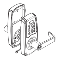
Instructions on how to operate the handleset from both inside and outside.

Related product manuals