==================================================================================================
ASSEMBLY
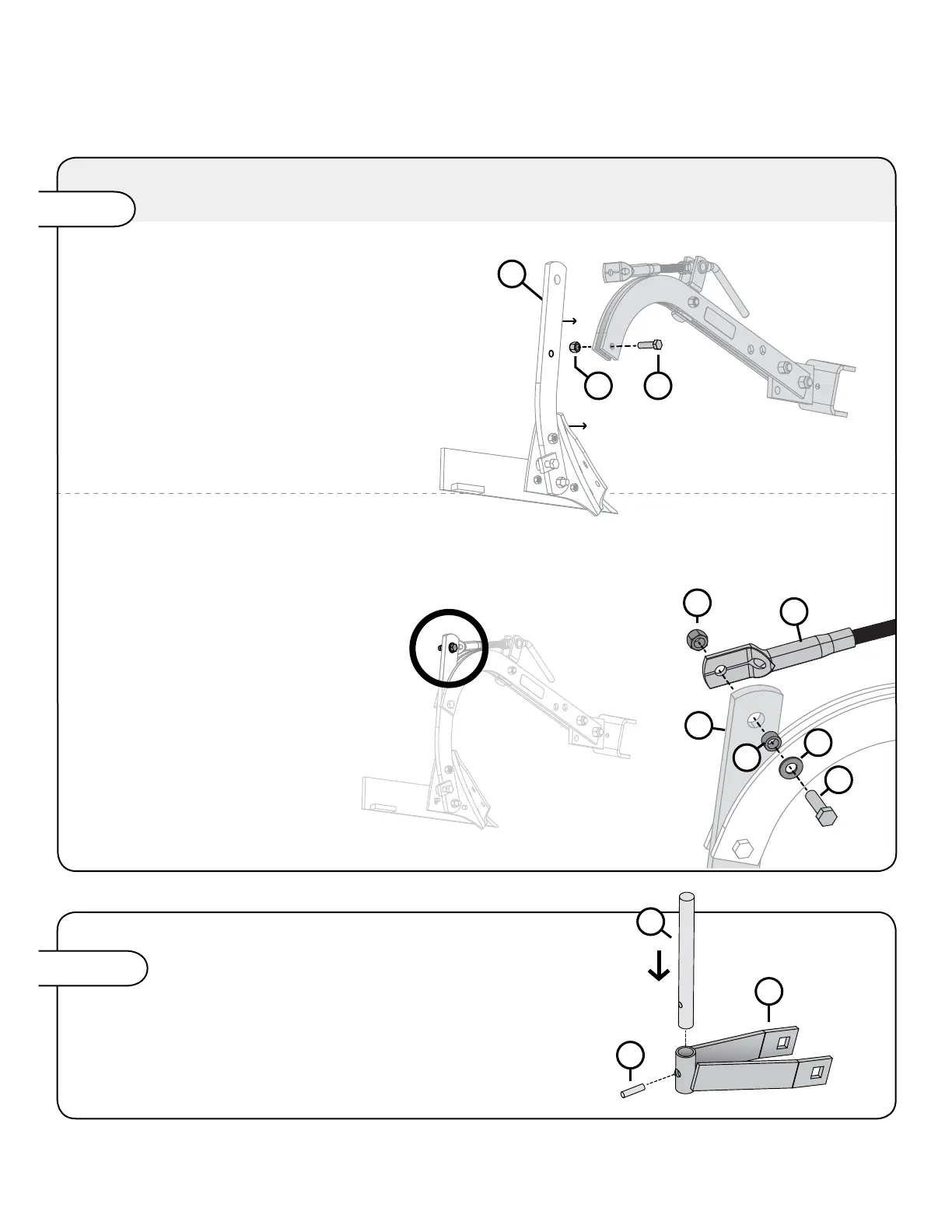
PLOW FRAME AND BOTTOM
9
the beams, as illustrated, aligning the
LOWER remaining opening of the
standard. Fasten together using:
29
2
9
11
Step 5
29
2
9
11
2
9
28
44
7
1615
17
equal amount of pin on each side.
Step 6-A
COULTER BLADE
16
17
15
28
44
Place a 9/16" spacer (7)
within the hole of the standard
2
Tighten these fasteners
so that the threaded tube is
free to pivot.
NOTE: The Plow comes partially assembled and attached to the Frog (Part 19).
The Plow parts are not illustrated on this step for better visibility on these assembly illustrations.
11 L-1043-3-BEnglish Manual