==================================================================================================
==================================================================================================
DO NOT RETURN PRODUCT IF YOU ARE MISSING PARTS.
Please Call: 1 (877) 728-8224
Contents of this page can be found in: Hardware Bag Z-1216-A
HARDWARE IDENTIFIER
Illustrations on this page
are to scale for faster
identication of hardware
during assembly.
Bolt:
Hex Head
1/2 x 1-1/ 2”
(x2) . . . . . . . . . .
1M1624P
28
Bolt:
Hex Head
1/2 x 1-3/4”
(x2) . . . . . . . .
1M1628P
29
Bolt: Plow
1/2 x 2"
(x1) . . . . . . . .
15M163 2P
35
1
Nut: Hex
Locking, 5/16” -18
(x3) . . . . . . . . . . . . . . . . . . .
B- 1674 P
39
Nut: Hex
5/8” (x2) . . . . . . . . .
30M2000P
3
Nut: Hex
Locking, 5/8”
(x2) . . . . . . . . . . . . . . . . .
B-1678 P
Spacer
5/8" ID x 1/2"
(x2) . . . . . . . . . . . .
P-597
26
Trunnion
(x1) . . . . . . . . . .
P-598 -01
27
Washer;
Flat, 5 /16”
(x3) . . . . . . . . . . . .
45 M1111P
42
Washer;
Flat, 5/8”
(x2) . . . . . . .
45M2121P
45
Washer;
Flat , 1/2 ”
(x1) . . . . . . . .
45M1717 P
44
4
English Manual L-1043-3-B
==================================================================================================
DO NOT RETURN PRODUCT IF YOU ARE MISSING PARTS.
Please Call: 1 (877) 728-8224
Hardware Bag Z-1216-C
HARDWARE IDENTIFIER
Illustrations on this page
are to scale for faster
identication of hardware
during assembly.
2 B-1677P Nut; Hex Lock, 1/2"-13 3
7 P-234 Spacer 1
14 P-262-01 Spacer, Plated 1
17 P-270 Pin; Spiral, 5/16 x 1-1/4" 1
30 1M2032P Bolt; Hex Head, 5/8-11 x 2
31 11M1012P Bolt; Carriage, 5/16 x 3/4" 3
32 10M1624P Bolt; Carriage, 1/2" x 1-1/2" 1
33 15M1216-R Bolt; Plow, 3/8-16 x 1" 2
36 30M1200P Nut; Reg Hex, 3/8"-16 2
38 30M1600P Nut; Hex, 1/2"-13 2
40 31M2000P Nut; Jam Hex, 5/8"-11 2
41 35M1600P Nut; Square Head, 1/2"-13 1
46 50M0420P Pin; Cotter, 1/8 x 1-1/4" 1
Hardware Bag Z-1216-B
6 P-172P Coulter Axle; Bolt, 5/8 x 4" 1
23 P-386P U-Bolt 1
24 P-387-01 Clamp, Coulter - Plated 1
Hardware Bag Z-1216-C
Ref # Part # Description Qty
1 B-1674P Nut; Lock, 5/16"-18 3
3 B-1678P Nut; Lock, 5/8"-11 2
26 P-597-01 Spacer; Coulter, 5/8" ID x 1/2" 2
27 P-598-01 Trunnion; Plated 1
28 1M1624P Bolt; Hex Head, 1/2" x 1-1/2" 2
29 1M1628P Bolt; Hex Head, 1/2" x 1-3/4" 2
35 15M1632P Bolt; Plow, 1/2-13 x 2" 1
39 30M2000P Nut; Hex, 5/8"-11 2
42 45M1111P Washer; Flat, 5/16" 3
44 45M1717P Washer; Flat, 1/2" 1
45 45M2121P Washer; Flat, 5/8" 2
Hardware Bag Z-1216-A
23
U-Bolt
(x1)
P-386P
6
Coulter Axle (x1)
P-172 P
24
Coulter Clamp (x1)
P-3 87- 01
6
English Manual L-1043-3-B
==================================================================================================
DO NOT RETURN PRODUCT IF YOU ARE MISSING PARTS.
Please Call: 1 (877) 728-8224
Contents of this page can be found in: Hardware Bag Z-1216-B
HARDWARE IDENTIFIER
Illustrations on this page
are to scale for faster
identication of hardware
during assembly.
Bolt; Carriage
5/16" x 3/4” (x3) . . . .
10M1012P
31
Bolt; Carriage, 1/2" x 1-1/2” (x1) . . . . . . . . . . . . . . . . . . . . . . . . . . . .
10M1624 P
32
Bolt: Hex Head 5/8" x 2” (x2) . . . . . . . . . . . . . . . . . . . . .
1M2032 P
30
Spacer
1/2" ID x 9/16"
(x1) . . . . . . . . . . . . . . . . .
P-234
7
Spacer
5/8" ID x 5/8"
(x1) . . . . . . . . . . . . . . . . .
P-262- 01
14
Drive Pin
5/16" x 1-1/4"
(x1) . . . . . . . . . . . . . . .
P-270
17
Pin; Cotter
1/8 x 1-1/4 "
(x1) . . . . . . . . . .
50M0420P
46
2
Nut; Hex Locking
1/2” (x3) . . . . . . . . .
B-167 7P
Nut; Reg Hex
3/8” -16 (x2) . . . . . . .
30M1200P
36
Nut; Hex
1/2” (x2). . . . . . . . . .
30M1600P
38
Nut;
Hex Jam
5/8” (x2) . . . . . . . . .
31M2000P
40
Nut; Square
1/2” (x1) . . . . . . . . . . .
35M1600P
41
Bolt; Plow
3/8" x 1” (x2) . . .
15M121 6- R
33
5
L-1043-3-BEnglish Manual
Additional info and videos are available on our website: brinly.com
DURING ASSEMBLY:
- Illustrations on pages 4-6 are to-scale. For faster
the hardware on top of these illustrations.
- Securely tighten all fasteners only AFTER plow assembly
has been completed, unless noted otherwise.
BEFORE ASSEMBLY:
- It is recommended that you carefully read this
owner's manual before starting assembly of the unit.
- Arrange each kind of hardware into groups.
- NOTE: Right hand (RH) and Left hand (LH) are determined
from the Operator's position while seated on the tractor.
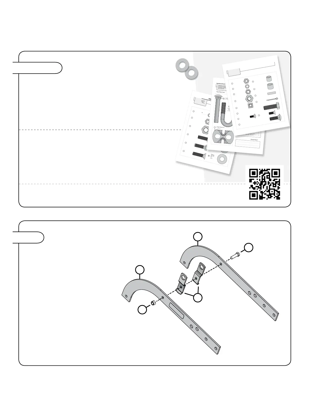
ASSEMBLY
Assembly Tips
PLOW FRAME
25
illustrated, against the inside of both
10
29
1/2" x 1-3/4"
2
Step 1
10
10
29
2
25
8 L-1043-3-BEnglish Manual
 Loading...