© BriskHeat
®
Corporation. All rights reserved.
4
LYNX
TM
System Instructions
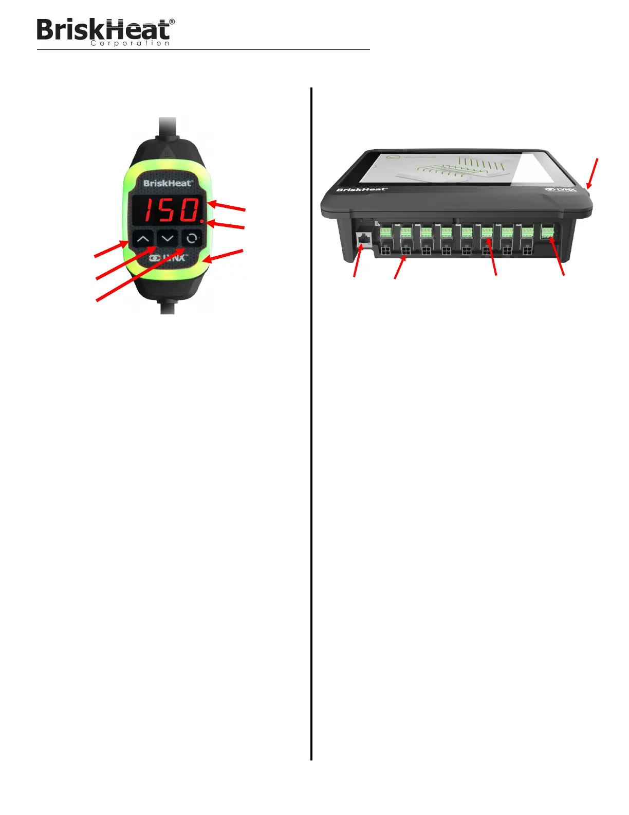
1
1.
2
3.
5.
2
4
6
1. Up Button
Used to move up through the Menu options and adjust param-
eters.
2. Down Button
Used to move down through the Menu options and adjust
parameters.
3. Function Button
Multi-use button used to access menu options, select and
enter new parameters, and save them. Refer to table 2 for
module programming instructions.
4. Display
Displays the current temperature, menu options, and parame-
ters.
5. Heater Output
Displays the current status of the heater output (on/off)
6. LED Indicator Light
Lighted display that provides the status of the LYNX Module.
Refer to table 1 for description of color codes.
1. Ethernet Port
Used to connect the Operator Interface Panel to an Internet
Connection or Local Area Network. (Required for Modbus
TCP/IP communication)
2. LYNX Module Communication Connector
Used to connect a LYNX Communication Harness to the Oper-
ator Interface Panel.
3. Dry-Contact Relay
Used to connect customer provided equipment to monitor
Alarms. Each Dry-Contact Relay corresponds with the com-
munication port above it.
4. Master Dry-Contact Relay
Used to connect customer provided equipment to monitor
Alarms in conjunction with a heating system, this relay is con-
nected to all 4-Pin connector ports.
5. USB Port
Used to connect a USB Storage Device* to the Operator Inter-
face Panel for uploading system drawings and exporting Data
acquired during operation with the panel.
* USB Devices must be formatted in FAT32 for proper communication
with the Operator Interface Panel.
4.
3
5
LYNX HARDWARE OVERVIEW