© BriskHeat
®
Corporation. All rights reserved.
8
LYNX
TM
System Instructions
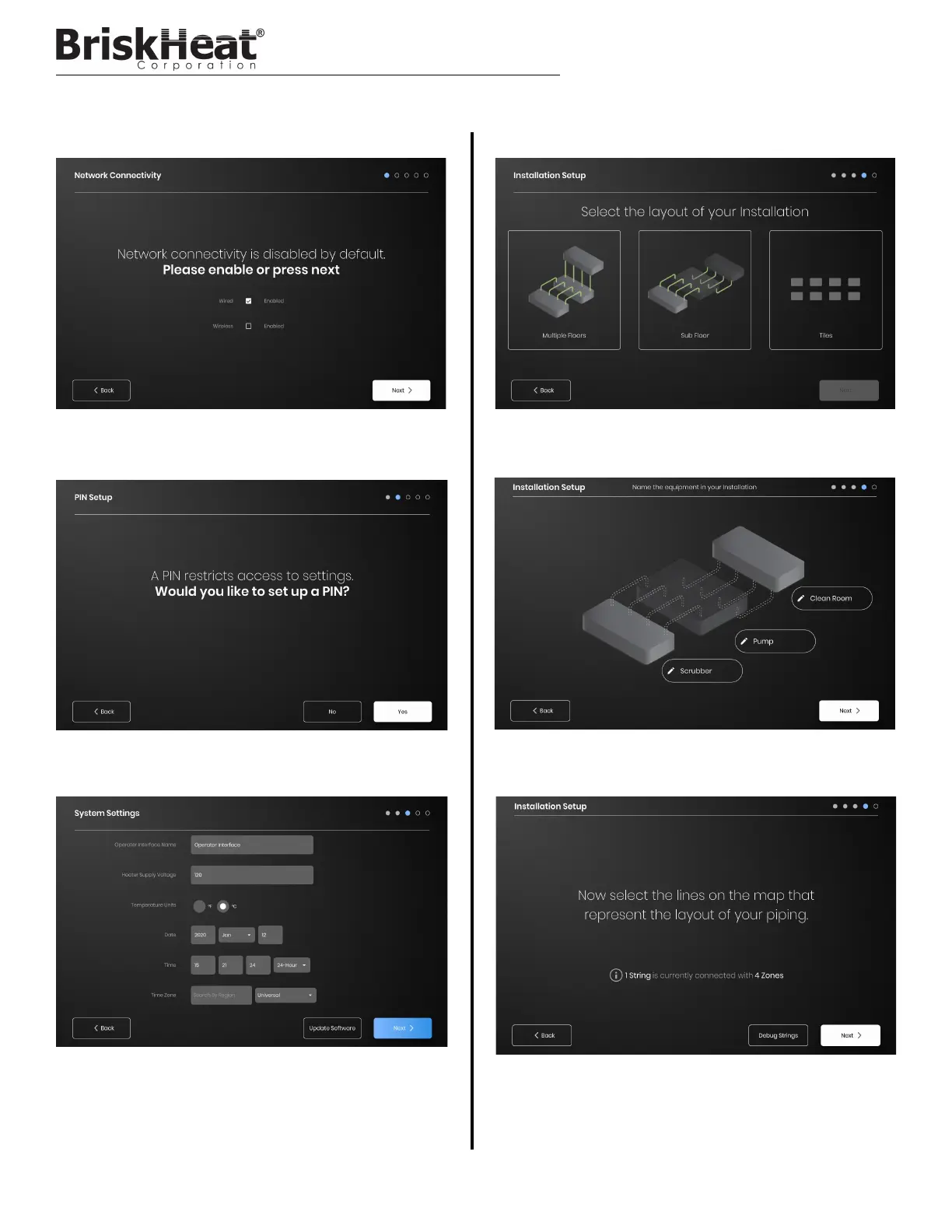
STEP 1: SYSTEM SETUP
Configure network connectivity settings.
Set a PIN to restrict access to the unit, if desired.
Assign the following values: Unit name, intended Supply Voltage,
Temperature Units, Date and Time.
STEP 2: FACILITY SETUP
Ensure that the number of detected Strings and Zones matches what
is plugged into the OI. If an error is present, the “Debug Strings” button
can help with identifying which Strings or Zones are having issues.
OPERATOR INTERFACE CONFIGURATION
Select the facility map that best resembles the layout of your facility:
-Multiple Floors
-Sub Floor
-Tile indication if no map representation is needed or desired
Assign names for each section of your facility by selecting the pen icon
next to each text box. A text box will appear enabling text editing.
Default names will be applied if no custom names are assigned.