INSTALLATION, START-UP & MAINTENANCE INSTRUCTIONS
1.0 INTRODUCTION .....................................................................................................................................4
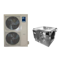
1.1 Brivis ICE R410a Inverter Range ............................................................................................................4
1.2 Safety / Warnings ....................................................................................................................................4
1.3 Codes / Regulations ................................................................................................................................5
2.0 COMPONENTS .......................................................................................................................................5
2.1 Indoor Unit (Cooling Coil) ........................................................................................................................5
2.2 Starting Collars ........................................................................................................................................6
2.3 P-Trap......................................................................................................................................................6
2.4 Outdoor Unit ............................................................................................................................................7
3.0 TYPICAL INSTALLATION .......................................................................................................................8
4.0 INDOOR UNIT INSTALLATION ..............................................................................................................8
4.1 Location ...................................................................................................................................................9
4.2 Condensate Drain / Safety Tray ..............................................................................................................9
4.3 Minimum Service Access.........................................................................................................................9
4.4 Electrical Connection ...............................................................................................................................9
4.5 System and Ductwork Design ...............................................................................................................11
4.6 Brivis Heater Thermistor position (if applicable)....................................................................................11
4.7 Filtration .................................................................................................................................................11
4.8 General Arrangement Drawings ............................................................................................................12
5.0 OUTDOOR UNIT INSTALLATION ........................................................................................................13
5.1 Location .................................................................................................................................................13
5.2 Electrical Connection .............................................................................................................................13
5.3 Thermostat Control Wiring.....................................................................................................................13
5.4 Wiring Diagrams ....................................................................................................................................14
5.5 General Arrangement Drawings & Clearance Requirements ...............................................................17
6.0 REFRIGERATION CHARGE & PIPE-WORK........................................................................................18
6.1 Piping Design.........................................................................................................................................19
6.2 Pipe-work connection ............................................................................................................................20
6.3 Expelling the air with the vacuum pump................................................................................................21
6.4 Charging the system..............................................................................................................................22
7.0 START-UP AND COMMISSIONING .....................................................................................................23
7.1 Sequence of Operation..........................................................................................................................24
7.2 Cooling Capacity Tables........................................................................................................................25
7.3 Specifications.........................................................................................................................................26
7.4 Commissioning Sheet............................................................................................................................27
 Loading...