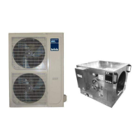
The Brivis Inverter Icebox is a refrigerated cooling split-only type air conditioner designed for integration with compatible Brivis Ducted Gas Heaters. It utilizes the existing heating system's ductwork and air circulation fan to distribute cool, filtered refrigerated air throughout a building. This system is intended for residential applications and is not designed for marine craft, houseboats, or similar environments.
Models and Compatibility:
The Icebox is available in several models, each with specific outdoor unit pairings and recommended Brivis Gas Ducted Heater models:
-
DONSC10Z71 (Outdoor Unit) / DINIB10Z7-L or DINIB10Z7-R (Indoor Unit):
- Nominal Cooling Capacity: 10 kW
- Rated Cooling Capacity (Range): 9.4 (4.8-10.1) kW
- Recommended Brivis Gas Ducted Heater Model: All Buffalo 20XA
-
DONSC13Z71 (Outdoor Unit) / DINIB13Z7 (Indoor Unit):
- Nominal Cooling Capacity: 13 kW
- Rated Cooling Capacity (Range): 12.4 (6.3-13.6) kW
- Recommended Brivis Gas Ducted Heater Model: All Buffalo 26
-
DONSC15Z71 (Outdoor Unit) / DINIB15Z7 (Indoor Unit):
- Nominal Cooling Capacity: 15 kW
- Rated Cooling Capacity (Range): 14.7 (7.5-16.0) kW
- Recommended Brivis Gas Ducted Heater Model: All Buffalo 26XA
The refrigerant used in these systems is R410A.
Installation Requirements and Safety:
Installation, maintenance, and removal of this appliance must be performed by an Authorised Person in accordance with:
- Manufacturer's Installation Instructions
- Current AS/NZS 3000, AS/NZS 1677.2, AS 4211.3, AS 4254, AS/NZS 5141, HB 276-2004
- Local Regulations and Municipal Building Codes, including local OH&S requirements
Failure to comply with these instructions may void the warranty and could result in service charges. It is crucial to inspect the appliance for any damage or discrepancies upon receipt, as damaged or incorrect appliances MUST NOT be installed or operated.
Safety Warnings:
- Always check the unit weight to ensure lifting equipment is adequate.
- Disconnect power to the unit before any work is performed.
- Do not remove access panels or doors until fans have completely stopped.
- Never enter a fan cabinet while the fan is running.
- Protect materials when welding or flame cutting, using suitable cloth to contain sparks and having a fire extinguisher readily available.
- Do not place articles on or against the appliance.
- Do not use or store flammable materials near the appliance.
- Do not spray aerosols in the vicinity of the appliance while it is in operation.
- Do not modify the appliance.
Key Features and Specifications:
Icebox Unit Dimensions (L x W x H):
- DINIB10Z7-L/R: 772 x 392 x 839 mm
- DINIB13Z7: 956 x 566 x 876 mm
- DINIB15Z7: 1026 x 566 x 876 mm
Packing Dimensions (L x W x H):
- DINIB10Z7-L/R: 870 x 395 x 842 mm
- DINIB13Z7: 1100 x 570 x 880 mm
- DINIB15Z7: 1170 x 570 x 880 mm
Weight (Net):
- DINIB10Z7-L/R: 35 kg
- DINIB13Z7: 45 kg
- DINIB15Z7: 50 kg
Electrical Specifications:
- Power Supply: 220~240-1-50 V-ph-Hz
- Maximum Input Current: <0.1 A
- Rated Input Power: 10 W
- Power Connection: Power Cord & Plug 2.5m (standard 10 Amp 220 to 240 Volt fixed switched socket outlet required)
Airflow:
- DINIB10Z7-L/R: 600 L/s (Rated), 459 L/s (Minimum)
- DINIB13Z7: 688 L/s (Rated), 550 L/s (Minimum)
- DINIB15Z7: 736 L/s (Rated), 620 L/s (Minimum)
Coil Static Pressure Drop:
- @Rated Airflow (Dry/Wet):
- DINIB10Z7-L/R: 95/118 Pa
- DINIB13Z7: 96/120 Pa
- DINIB15Z7: 88/110 Pa
- @Minimum Airflow (Dry/Wet):
- DINIB10Z7-L/R: 56/70 Pa
- DINIB13Z7: 62/77 Pa
- DINIB15Z7: 62/78 Pa
Duct Connection (Outlet/Inlet):
- DINIB10Z7-L/R: Ø350 mm
- DINIB13Z7: Ø350 mm
- DINIB15Z7: Ø400 mm
Moisture Removal:
- DINIB10Z7-L/R: 2.2 L/h
- DINIB13Z7: 2.9 L/h
- DINIB15Z7: 3.4 L/h
Condensate Drain Pipe Diameter: 3/4" BSPM
Refrigerant Pipe Connections (Liquid / Gas):
- DINIB10Z7-L/R, DINIB13Z7: Ø9.5 / Ø15.9 mm
- DINIB15Z7: Ø9.5 / Ø19.0 mm
Operating Temperature Limits: 19~32 °C
Usage Features:
- Airflow Orientation: The 10kW Icebox models (DINIB10Z7-L and DINIB10Z7-R) are available in left and right-hand orientations, respectively. The 13kW and 15kW Icebox models (DINIB13Z7 and DINIB15Z7) are factory-set for left-hand orientation but can be converted to right-hand orientation by relocating the 'Top Rail' and 'Pop Cover Plate'.
- Integrated Cooling: The Icebox uses the existing heating system's fan and ductwork, simplifying installation and reducing the need for separate air distribution components.
- Condensate Drainage: All models include a 3/4" BSPM thread for connecting a drainpipe, which must have a continuous downward grade of not less than 1:50 to prevent pooling and corrosion.
- Thermistor Location (BX5 Models): For BX5 models, the thermistor needs to be repositioned to the in-cabinet thermistor arm, ensuring the wiring is safely routed away from heat sources.
- Communication Cable: A 2-core shielded communication cable (field supplied) is required between the Icebox unit (Terminals S1 & S2) and the outdoor condenser unit (Terminals S1 & S2), with the shield earthed at the condenser end only.
- Control Wiring: 24-volt control wiring is installed from the Icebox electric box (Terminals A1, A2) to the Heater (StarPro series) or Brivis Thermostat.
Maintenance Features:
- Service Clearances: A minimum clearance of 750mm on the sides and 500mm from the front of the unit, extending vertically one meter above the heater roof, is required for servicing.
- Filtration: A filter must be fitted into the system and should be easily accessible for regular cleaning. Refer to the guidelines for return air filter grilles accompanying the Gas Ducted Heater.
- Nitrogen Holding Charge: Icebox coils are supplied with a nitrogen holding charge (400kPa to 700kPa) to protect against leaks during transport. This charge must be checked prior to installation.
- Regular Servicing: Rinnai recommends that this appliance be serviced every 2 years by a qualified technician.
Ductwork Design:
Good duct design and sizing are essential for efficient operation. Key considerations include:
- Airtight and Insulated Ductwork: Ductwork should be airtight and have a minimum insulation rating of R1.0.
- Proper Sizing and Smooth Bends: Ducts should be sized correctly with smooth curves and bends to ensure efficient, quiet airflow.
- Register and Diffuser Design: Registers and diffusers should be large enough and designed to minimize noise while providing the correct distribution pattern.
- Return Air System: A positive return air system with a grille large enough to handle the full air capacity at low noise levels is required.
- Air Filtration: Adequate air filtration must be provided.
- Outlet/Inlet Placement: If high-level outlets (e.g., ceiling diffusers) are used, the return air inlet should be at a low level.
- Downstream Ductwork: A minimum of 1m, or preferably 2½ times the duct diameter, of straight ductwork must be installed immediately downstream of the Icebox unit before any divergence or branch-take-offs to avoid compromising airflow, system performance, and reliability.
- Icebox Coil Placement: The Icebox coil unit must never be placed in the return air part of the duct system, as this can lead to condensation, corrosion, and damage to vital components in the Heater.
The Brivis "SuperSizeGuide" / Brivisize, Technical Data Sheets, or HB276 should be consulted for estimating cooling requirements and system design. All ductwork and fittings must be insulated, and fire-rated duct may be mandatory under some building codes.