4.8 Wiring the Icebox to a BX3 & BX5 heater
Terminals ‘A1’ & ‘A2’ are not polarity sensitive and the connecting conductors shall be routed through the
grommet adjacent to the terminal block (C Y G W R TW1 TW2). The end panel will need to be
temporarily removed to assist with routing conductors back to the control board.
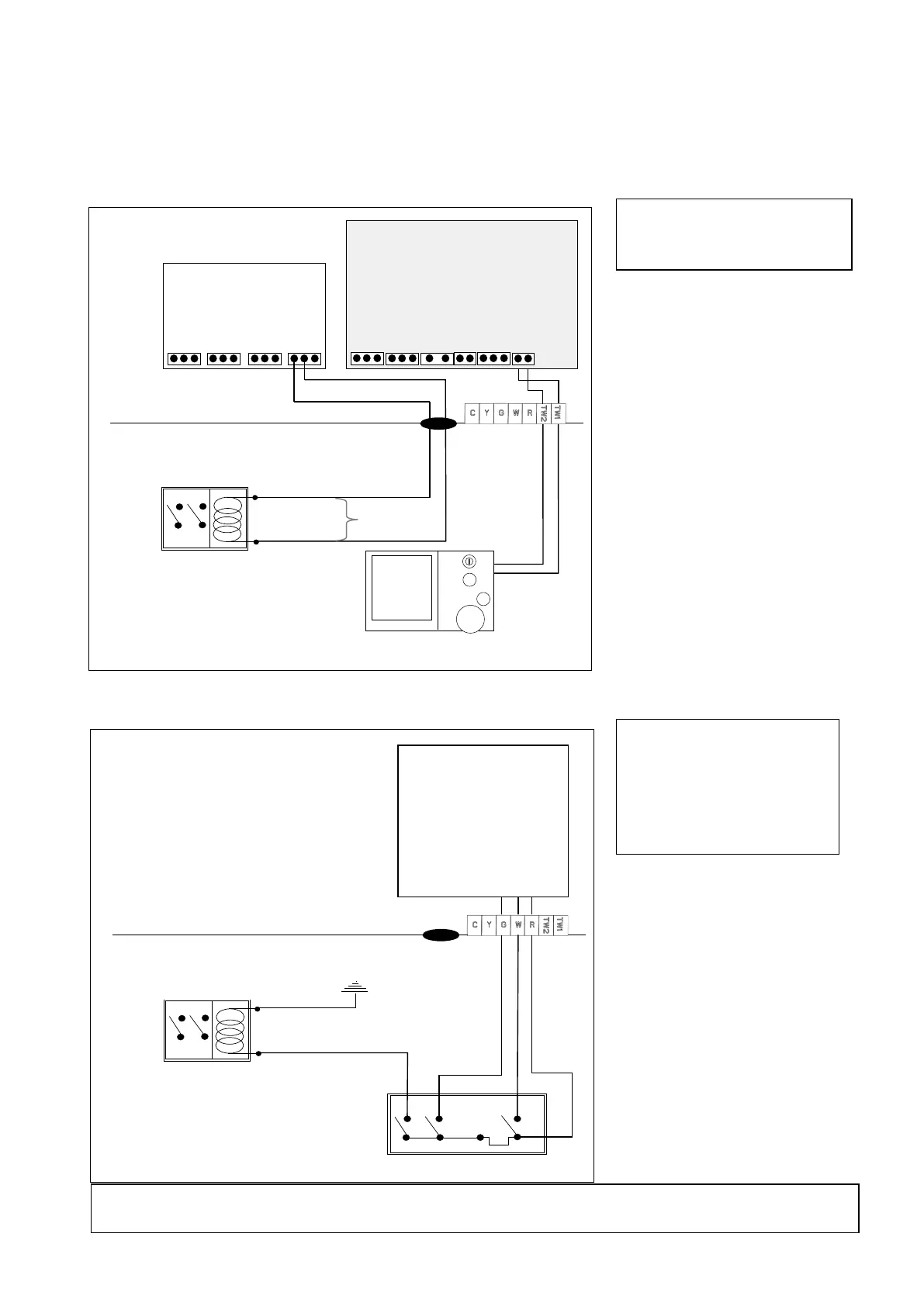
Diagram 19: BX5 Wiring circuit for NG-2A to Icebox and Networker
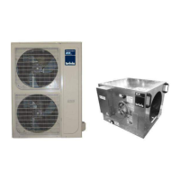
Diagram 20: BX3 Wiring circuit for HCDSI24 to Icebox and Brivis Programmable Thermostat
Icebox PCB relay connections
installation instruction
supplied with “B063033
Loom add-on relay
classic”.
A2) at ‘516 Zone Module’
A2) at Brivis Programmable
Thermostat and CDU for
earth. For ‘G’ connection
additional relay is required
Note: Early model Buffalos may have on board provisions for add-on cooling. For more information contact
the Brivis Technical Support Group (TSG) on 1300 361 295.
Icebox PCB relay connections
Heater Parameter “H01 ID07:5”
Electronic Control Module
ADD-ON
Refrig