Do you have a question about the Broan 741SN and is the answer not in the manual?
| Airflow | 70 CFM |
|---|---|
| Duct Size | 4 inches |
| Voltage | 120 V |
| Mounting Type | Ceiling |
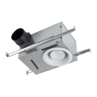
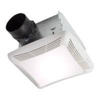
| Housing Material | Galvanized Steel |
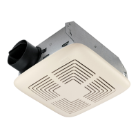
| Blade Material | Plastic |
| Type | Ceiling |
Essential safety instructions for installation and use, covering fire, shock, injury risks, and proper handling.
Important cautions regarding use, installation location, mounting, and maintenance to prevent damage and ensure safety.
Mounting the housing directly to a 2x6 or larger joist, with discharge parallel to joists.
Mounting housing to a 2x4 truss, requiring additional framing, discharge parallel to joists.
Mounting housing to an 'I' joist, needs extra framing, discharge parallel to joists.
Mounting to additional framing with discharge perpendicular (90°) to joists.
Mounting to a 2x4 truss with extra framing, discharge 90° to joists.
Mounting to an 'I' joist with additional framing, discharge 90° to joists.
Mounting housing in suspended ceilings using wires for a 3-point mount.
Step-by-step guide for installing the housing in new construction, including positioning and securing.
Instructions for installing the housing in existing construction, involving cutting an opening and securing.
Guidance on connecting the 4" duct to the housing and ensuring a secure, airtight connection with damper.
Instructions for wiring the unit, including connections to the switch box and receptacles.
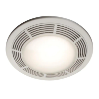
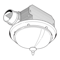
Steps for attaching the grille pan, washer, rod, and glass shade, including bulb installation.
Instructions for cleaning the glass shade, grille pan, and fan assembly, emphasizing safety.
Procedure for replacing bulbs, including removing the shade and securing the finial nut.
Note stating the motor is permanently lubricated and should not be oiled or disassembled.
List of available service parts with their corresponding part numbers and descriptions.
Details of the one-year limited warranty, including coverage, exclusions, and claim procedures.