E
Elizabeth KimSep 10, 2025
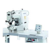
What causes incorrect work clamp lift amount on Brother BE-438B?
- KKathryn BrownSep 12, 2025
An incorrect work clamp lift amount or button clamp lift amount can be caused by: * Incorrect position of the work clamp arm lever plate (button clamp holder hook assembly); adjust the work clamp (button clamp) lift amount. * Incorrect position of the work clamp arm lever; adjust the work clamp (button clamp) lift amount.