Home
Brother
Sewing Machine
BE-438D
Brother BE-438D - User Manual
66 pages
Manual
Specs
Ask a question
Save Page as PDF
To Next Page
To Next Page
Loading...
KE-430D
ELECTRONIC DIRECT
DRIVE LOCKSTITCH
BAR T
ACKER
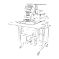
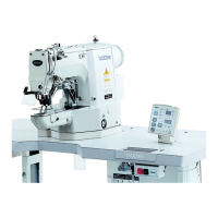
BE-438D
ELECTRONIC DIRECT
DRIVE LOCKSTITCH
BUTT
ON SEWER
2
Table of Contents
Main Page
Default Chapter
3
Safety Instructions
3
Maintenance and Inspection
5
Table of Contents
7
1 Names of Major Parts
8
2 Specifications
9
Machine Specifications
9
Program List (KE-430D)
10
For Eyelet Buttonhole
14
Circular Stitching
14
L-Pattern Tacking
14
Program List (BE-438D)
15
3 Installation
18
Table Processing Diagram
18
Installing the Control Box
19
Installing the Oil Pan
19
Installing the Machine Head
20
Installing the Operation Panel
21
Installing the Treadle Unit
21
Installing the Cotton Stand
22
Installing the Button Tray (BE-438D)
22
Installing the Eye Guard
22
Connecting the Cords
23
Connecting the Ground Wire
25
Installing the
26
Lubrication
27
Connecting the Power Cord
28
Starting up
29
4 Preparation before Sewing
30
Installing the Needle
30
Threading the Upper Thread
30
Winding the Lower Thread
32
Installing the Bobbin Case
33
Thread Tension
33
Lower Thread Tension
33
Upper Thread Tension
34
Thread Nipper Device
35
Inserting the Button (BE-438D)
37
Adjusting the Button Clamp (BE-438D)
37
Installing the Accessory Spring (BE-438D)
37
5 Using the Operation Panel (Basic Operations)
38
Name and Function of each Operation Panel Item
38
Setting the Program Number
40
Setting the X-Scale and Y-Scale
40
Setting the Sewing Speed
40
Checking the Sewing Pattern (KE-430D)
41
Checking the Sewing Pattern (BE-438D)
42
Adjusting the Work Clamp / Button Clamp Lift Amount
43
6 Using the Operation Panel
44
(Advanced Oeprations)
44
List of Advanced Functions
44
Setting Memory Switches
45
List of Memory Switches
46
Using the Lower Thread Counter
47
Using the Production Counter
48
Using User Programs
49
Using Cycle Programs
52
Direct Selection
55
Loading Additional Sewing Data
55
7 Sewing
56
8 Maintenance
57
Cleaning the Rotary Hook
57
Cleaning the Control Box Air Inlet Ports
58
Draining the Oil
58
Cleaning the Eye Guard
58
Checking the Needle
58
Lubrication
58
Applying Grease (Work Clamp: KE-430D)
59
Applying Grease (When "GREASEUP" Appears)
59
Grease Application Locations
61
Resetting the Grease up Counter
61
9 Table of Error Codes
62
Instruction Manual
66
Other manuals for Brother BE-438D
Instructions
4 pages
Need help?
Do you have a question about the Brother BE-438D and is the answer not in the manual?
Ask a question
Brother BE-438D Specifications
Print Specification
General
Model
BE-438D
Stitch Length
5mm
Maximum Stitch Width
7mm
Maximum Stitch Length
5mm
LCD Display
Yes
Needle Threader
Automatic
Needle Position
Yes
Related product manuals
Brother BE-438C
67 pages
Brother BE-438F
90 pages
Brother BE-438B
198 pages
Brother BE-438FX
90 pages
Brother BE-438HX
108 pages
Brother BE-438HS
108 pages
Brother BE-1204B
262 pages
Brother BE-1204C
7 pages
Brother BE-0901E-AC
16 pages
Brother BE-1201B-AC
246 pages
Brother BE-0901E-AC-PC
246 pages
Brother BE-1201B AC-PC
119 pages