Do you have a question about the Brother HL-L2395DW and is the answer not in the manual?
Explains the meaning of conventions like WARNING, CAUTION, IMPORTANT, NOTE, etc.
Provides instructions for safe operation, including electrical hazards and power cord safety.
Details safety guidelines for using the power cord, including grounding and extension cord usage.
Warns about laser product safety and precautions when servicing the laser unit.
Offers additional safety advice related to optical systems and laser beams.
Provides standard telephone and FCC notices applicable to models sold in the United States.
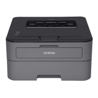
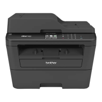
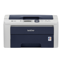
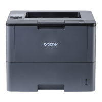
Comparative table of model functions, including features like LAN, duplex print, and paper input.
Details network connectivity types (wired/wireless) and node types for various models.
Provides machine life, part life, MTBF, MTTR, and maintenance parts life specifications.
Lists toner cartridge yields, drum unit life expectancy, and shelf life information.
Specifies media types, paper input, media weight, and media size for ADF.
Details fax specifications like modem speed, transmission speed, and ITU-T group.
Provides copy speed and first copy out time specifications for different models.
Details scanner resolution, scanning speed, and duplex scanning capabilities.
Explains the purpose of troubleshooting and provides precautions for service personnel.
Outlines essential precautions to prevent secondary problems during troubleshooting.
Lists essential checks regarding operating environment, power supply, paper, and consumables.
Includes cross-section drawings of the printer and scanner parts, and paper feeding paths.
Illustrates the internal components of the printer part and scanner part.
Details the manual feed slot models and MP models printer parts with diagrams.
Provides diagrams for SX models and DX models scanner parts.
Explains the paper feeding mechanisms for the printer part and scanner part.
Details the operation and location of various parts within the machine.
Presents a block diagram showing the interconnections between major components and PCBs.
Illustrates the main components of the machine, such as ADF unit and Panel unit.
Lists error codes, messages, and descriptions to help diagnose machine malfunctions.
Provides a comprehensive list of error codes, their descriptions, and corresponding reference pages.
Lists error messages displayed on the LCD for both LCD and touch panel models.
Provides step-by-step guidance for resolving common machine errors and problems.
Details the cause and remedy for specific error codes encountered by the machine.
Addresses various paper feeding issues like no paper, multiple sheets, jams, and wrinkles.
Guides on identifying and resolving various scanning image defects.
Addresses problems related to printing from a computer or driver issues.
Provides solutions for issues encountered when making a print or connecting to an access point.
Offers solutions for problems related to the LCD, LED, and panel operations.
Addresses problems related to toner cartridge detection and drum unit errors.
Addresses troubleshooting steps for fuser unit failures.
Details troubleshooting steps for laser unit failures.
Offers solutions for problems related to the Main PCB and memory issues.
Addresses various issues related to document feeding in the ADF.
Provides troubleshooting steps for document jams in the ADF cover and ADF.
Guides on identifying and resolving various scanning image defects.
Addresses issues related to sending, receiving, and communication errors for fax.
Covers other problems not fitting into previous categories, like printing or firmware issues.
Provides essential warnings and precautions to follow during disassembly and reassembly.
Lists various screw types used in the machine with their specifications.
Provides screw locations, types, quantities, and tightening torque values.
Specifies lubricating oil types, points, and quantities for lubrication.
Illustrates and lists gears used in the machine with their part numbers.
Shows diagrams of harness routing for various internal components.
Presents a flowchart outlining the sequence of disassembly and reassembly procedures.
Provides detailed step-by-step instructions for disassembling various parts of the machine.
Provides steps for removing the fuser unit and its associated harnesses.
Provides steps for disconnecting harnesses and removing the Main PCB ASSY.
Details procedures after replacing the Main PCB ASSY, including firmware and settings.
Covers checking and installing sub and main firmware versions.
Details how to initialize the EEPROM of the Main PCB ASSY using function code 01.
Covers setting spec code, serial number, and laser unit adjusted values.
Provides instructions for adjusting the touch panel using function code 61.
Explains how to acquire white level data and set CIS scan area using function code 55.
Details procedures after replacing the Low-Voltage Power Supply PCB ASSY.
Details procedures after replacing the Laser Unit.
Details procedures after replacing the Panel Unit or Panel Control PCB.
Details procedures after replacing ADF, CIS units, or Document Scanner Unit.
Describes the purpose and usage of function codes for maintenance and diagnostics.
Explains methods to enter maintenance mode for service personnel.
Lists all maintenance mode functions with their codes and corresponding refer-to pages.
Provides detailed explanations and operating procedures for various maintenance mode functions.
Explains how to check the operation of sensors, solenoids, and clutches using function code 32.
Provides instructions for adjusting the touch panel using function code 61.
Presents the detailed wiring diagram of the machine's electrical components.
States that there are no parts that require periodic replacement.
Describes the serial number labels on the printer, including their location and format.
Provides procedures for returning user settings to default on touch and non-touch panel models.
Guides on installing the maintenance printer driver on Windows 7/8/8.1/10.
| Duplex printing | Yes |
|---|---|
| Print technology | Laser |
| Maximum resolution | 2400 x 600 DPI |
| Duplex printing mode | Auto |
| Time to first page (black, normal) | 8.5 s |
| Print speed (black, normal quality, A4/US Letter) | 36 ppm |
| Copier resize | 25 - 400 % |
| Maximum copy resolution | 600 x 600 DPI |
| Maximum number of copies | 99 copies |
| N-in-1 copy function (N=) | 2, 4 |
| Time to first copy (black, normal) | 10 s |
| Scanner type | Flatbed scanner |
| Input color depth | 30 bit |
| Output color depth | 24 bit |
| Input grayscale depth | 10 bit |
| Output grayscale depth | 8 bit |
| Maximum scan resolution | 19200 x 19200 DPI |
| Optical scanning resolution | 1200 x 1200 DPI |
| Faxing | No |
| Digital sender | - |
| Printing colors | Black |
| Maximum duty cycle | 15000 pages per month |
| Number of print cartridges | 1 |
| Page description languages | BR-Script 3, PCL 6, PDF 1.7 |
| Sustainability certificates | ENERGY STAR |
| Display | LCD |
| Control type | Touch |
| Display diagonal | 2.7 \ |
| Market positioning | Home & office |
| Internal memory | 128 MB |
| Processor frequency | 600 MHz |
| Sound pressure level (printing) | 50 dB |
| Paper input type | Paper tray |
| Total input capacity | 250 sheets |
| Total output capacity | 100 sheets |
| Multi-Purpose tray input capacity | 1 sheets |
| Paper tray media types | Bond paper, Envelopes, Labels, Plain paper |
| Paper tray media weight | 60 - 163 g/m² |
| ISO A-series sizes (A0...A9) | A4, A5, A6 |
| ISO B-series sizes (B0...B9) | B5, B6 |
| Multi-purpose tray media types | Envelopes, Executive, Legal, Letter, Letterhead |
| Maximum ISO A-series paper size | A4 |
| Multi-Purpose Tray media weight | 60 - 230 g/m² |
| Paper tray media weight (imperial) | 16 - 43 lbs |
| Multi-Purpose Tray media weight (imperial) | 16 - 61 lbs |
| Recommended monthly print volume | 2000 pages |
| Wi-Fi standards | 802.11b, 802.11g, Wi-Fi 4 (802.11n) |
| Cabling technology | 10/100Base-T(X) |
| Security algorithms | 64-bit WEP, 128-bit WEP, WPA-PSK, WPA2-PSK |
| Ethernet LAN data rates | 10, 100 Mbit/s |
| Mobile printing technologies | Apple AirPrint, Brother iPrint & Scan, Google Cloud Print, Mopria Print Service |
| Supported network protocols (IPv4) | ARP, RARP, BOOTP, DHCP, APIPA (Auto IP), WINS/NetBIOS Name Resolution, DNS Resolver, mDNS, LLMNR Responder, LPR/LPD, Custom Raw Port/Port 9100, IPP, FTP Client and Server, TELNET Server, SNMPv1/v2c/v3, HTTP Server, TFTP Client and Server, SMTP Client, ICMP, Web Services (Print/Scan) |
| Supported network protocols (IPv6) | NDP, RA, DNS Resolver, mDNS, LLMNR Responder, LPR/LPD, Custom Raw Port/Port 9100, IPP, FTP Server, SNMPv1/v2c, TFTP Client and Server, SMTP Client, ICMPv6, LLTD Responder, Web Services (Print/Scan) |
| Included cartridge capacity (black) | 700 pages |
| Quantity per pack | 1 pc(s) |
| Storage temperature (T-T) | 0 - 40 °C |
| Operating temperature (T-T) | 10 - 32 °C |
| Storage relative humidity (H-H) | 35 - 85 % |
| Operating relative humidity (H-H) | 20 - 80 % |
| AC input voltage | 120 V |
| AC input frequency | 50 - 60 Hz |
| Power consumption (off) | 0.02 W |
| Power consumption (ready) | 43.5 W |
| Power consumption (sleep) | 5.1 W |
| Power consumption (copying) | 490 W |
| Power consumption (printing) | 450 W |
| Power consumption (average operating) | - W |
| Depth | 272 mm |
|---|---|
| Width | 410 mm |
| Height | 398.5 mm |
| Weight | 10300 g |