Do you have a question about the Brother HLL3290CDW and is the answer not in the manual?
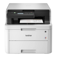
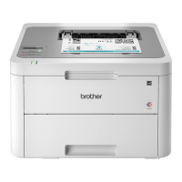
Comparative table of functions for various Brother MFC and HL models.
Specifies wired and wireless network node types for all models.
Details machine life, part life, MTBF, MTTR, and max monthly print volume.
Lists toner, drum unit, belt unit, and waste toner box specifications.
Details media types, weights, and input/output specifications for various paper types.
Provides specifications for modem speed, transmission speed, and fax types.
Specifies copy speed, first copy out time, and print resolution for different models.
Lists optical and interpolated resolution and scanning speeds for different models.
Explains the purpose of troubleshooting procedures and sample troubles.
Outlines essential safety precautions to prevent secondary problems during maintenance.
Lists checks for operating environment, power supply, paper, and consumable parts.
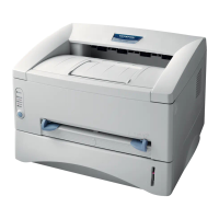
Provides a general overview of the machine's main internal components.
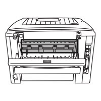
Illustrates detailed cross-section drawings of the printer and scanner parts.
Shows a cross-section of the printer part, detailing manual feed components.
Illustrates the paper feeding paths for manual feed and MP tray.
Details the manual feed paper path within the printer mechanism.
Explains the operation and location of various parts like sensors, rollers, and actuators.
Illustrates the interconnections between major machine components.
Provides an exploded view of the machine's main internal components.
Introduces the machine's self-diagnosis function for error reporting.
Lists and describes various error codes, their causes, and references.
Details error messages displayed on the LCD and their descriptions.
Lists error messages and their remedies for non-touch panel models.
Lists error messages and their remedies for touch panel models.
Lists causes and references for various communication error codes.
Provides guidance for troubleshooting machine errors and malfunctions.
Offers solutions for common paper feeding issues.
Provides user checks and steps to resolve no paper feeding issues from Tray 1.
Guides users on identifying and resolving image quality issues.
Visual examples of common image defects like light print, streaks, and ghosting.
Provides troubleshooting steps for specific image defects like light print.
Addresses issues related to software, drivers, and machine communication.
Provides steps for troubleshooting when data cannot be received by the machine.
Guides on resolving network connectivity and access point issues.
Steps to troubleshoot network printing problems.
Solutions for issues preventing connection to a wireless access point.
Addresses issues with the LCD display or LED indicators on the control panel.
Troubleshooting steps when the LCD screen is blank.
Steps to resolve issues where LED indicators are not functioning.
Guides on resolving issues related to toner cartridge and drum unit detection.
Steps to take when the machine does not detect a new toner cartridge.
Provides troubleshooting steps for fuser unit failures.
Details causes and remedies for fuser unit malfunctions.
Guides on resolving issues with the LED ASSY.
Troubleshooting steps for LED ASSY failures and related components.
Addresses issues related to main PCB and other electronic boards.
Troubleshooting steps for a malfunctioning main PCB.
Guides on resolving issues with document feeding through the ADF.
Steps to troubleshoot when no document is fed into the ADF.
Solutions for when the ADF feeds multiple documents at once.
Guides on identifying and resolving various image quality problems.
Visual examples of common image defects like light print, streaks, and ghosting.
Provides troubleshooting steps for specific image defects like light print.
Guides on resolving issues related to sending and receiving faxes.
Troubleshooting steps when the machine fails to send a fax.
Addresses miscellaneous problems not covered in other sections.
Troubleshooting steps when printing from a computer fails.
Essential warnings and precautions for safe disassembly and reassembly.
Details the packing components and procedure for shipping or storage.
Lists common screw types used in the machine with their specifications.
Provides a table of screw types, quantities, and their specified torque values.
Specifies lubricating oils, points, and quantities for specific parts.
Illustrates the layout and names of the machine's gears.
Shows the routing of electrical harnesses for various machine units.
Provides a flowchart outlining the sequence of disassembly steps for major parts.
Details the step-by-step process for disassembling machine components.
Steps for disconnecting cables and removing accessories before disassembly.
Instructions for removing the paper tray and T1 separation pad assembly.
Step-by-step guide to removing the back cover assembly and its stopper arms.
Instructions for removing the rear flapper sub assembly from its bosses.
Guides on removing the fuser cover and fuser unit, including screw and hook details.
Instructions for removing the cord hook from its locations.
Steps for removing the left side cover, including screws and hooks.
Instructions for removing the right side cover, including screws and hooks.
Guides on releasing hooks to remove the lower back cover.
Steps for removing the document scanner unit, including shield plates and ground wires.
Guides on removing the ADF unit and its associated components.
Detailed steps for removing the ADF unit itself.
Instructions for removing the document separation roller assembly from the ADF.
Steps for removing the ADF separation holder assembly from the ADF unit.
Guides on removing the second side CIS unit and its flat cable.
Steps for removing the document detection and scanning position sensor PCBs.
Instructions for removing the document cover assembly.
Steps for removing the panel unit and disconnecting its flat cable.
Detailed disassembly of the touch panel unit, including key PCB, LCD, and shield cover.
Instructions for removing the panel PCB and LCD assembly for non-touch models.
Guides on removing the panel flat cable and first side CIS unit/cable.
Steps for removing the modem flat cable and modem PCB.
Instructions for removing the joint cover assembly, including ground wire and arm.
Guides on removing the LED unit and its associated components.
Steps for removing the speaker unit, including harness and spring.
Instructions for removing the NFC PCB and associated covers.
Guides on removing the LED control PCB and its shield plate.
Steps for removing the LED ASSY and its flat cables.
Instructions for removing MP paper guide, MP cover, and USB host PCB.
Steps for removing the MP roller holder assembly.
Guides on removing the MP unit, including harnesses and paper feed guide.
Instructions for removing the manual feed cover and USB host PCB.
Steps for removing the high-voltage power supply PCB and develop release sensor PCB.
Instructions for removing the fan and its harness.
Steps for removing the WLAN PCB and its cap.
Guides on disconnecting harnesses and removing the main PCB.
Instructions for removing the cartridge sensor relay flat cable and PCB.
Guides on removing multiple components including clutch, drive units, and flat cables.
Steps for removing clutches, bearings, and the paper feed drive unit.
Instructions for removing the eject sensor PCB and its associated harnesses.
Guides on removing the roller holder assembly.
Steps for removing the paper feed unit.
Instructions for removing the paper eject assembly, including gears and arms.
Guides on removing the duplex tray, DX drive cover, and gears.
Steps for removing the low-voltage power supply PCB and its related components.
Instructions for removing registration mark sensors and related PCBs.
Actions and preparations required after replacing the main PCB.
Steps for adjustments after replacing the registration mark sensor or LED ASSY.
Procedure for resetting counters after replacing the low-voltage power supply PCB.
Steps for adjusting the touch panel and checking LCD operation after replacement.
Actions for acquiring white level data and performing scanning checks after replacement.
Procedure for resetting printed pages counter after replacing the fuser unit.
Steps for resetting printed pages counter after replacing a PF kit.
Introduction to the maintenance mode for machine checks and adjustments.
Detailed instructions on how to access the maintenance mode.
Procedures for service personnel to enter the maintenance mode.
Explains how end-users can access certain maintenance functions.
A comprehensive list of all available maintenance mode functions and their references.
Detailed explanations of various maintenance mode functions.
Function to initialize EEPROM parameters for service and user support.
Function to set the machine to its shipping state, affecting software availability.
Tests the performance of the automatic document feeder by counting scanned pages.
Prints test patterns to check monochrome image and print quality.
Allows setting various functions via worker switches and printing their configuration.
Table detailing worker switches and their functions for system configuration.
Verifies the normal operation of the control panel's LCD display.
Checks the functionality of all control panel keys for normal operation.
Saves network configuration information to a USB flash memory.
Checks firmware, program, and sum information versions.
Verifies the operational status of various machine sensors.
Checks the connection status of the wired LAN interface.
Allows changing settings for various print functions like resolution and paper size.
A broad function to adjust various print parameters and settings.
Adjusts the print position in horizontal and vertical directions.
Transfers fax data, logs, or reports to another machine.
Adjusts the scanning start and end positions for ADF and FB.
Acquires white level data and sets the CIS scan area for accurate scanning.
Verifies toner cartridge support, color, and destination via the sensor.
Calibrates the touch panel for accurate input.
Adjusts color registration, manually or automatically, to correct misregistration.
Conducts paper feed and eject tests by printing various patterns.
Prints LED ASSY test patterns to check for failures.
Prints a frame pattern on one side of the paper to check for flaws.
Prints a frame pattern on both sides of the paper for flaw checking.
Prints test patterns to check the develop roller or exposure drum condition.
Adjusts density sensor sensitivity to correct print density issues.
Performs consecutive adjustments for density, bias voltage, and color registration.
Customizes machine settings for language, functions, and worker switches by spec code.
Prints maintenance data like consumable levels and replacement counts.
Checks the fan operation by switching speeds among 100%, 67%, 50%, and OFF.
Deletes fax data stored in the machine's memory.
Displays machine logs, error logs, and serial numbers on the LCD.
Shows the latest error code encountered by the machine on the LCD.
Corrects developing bias voltage to fix color density issues in prints.
Sends error lists to service personnel for remote analysis of fax problems.
Resets counters for consumable parts after replacement, like fuser or PF kit.
Exits maintenance mode and restarts the machine to its ready state.
Provides access to additional service functions beyond standard maintenance.
Switches the automatic color registration function ON or OFF.
Prints a list of communication errors for troubleshooting.
Provides a detailed wiring diagram of the machine's electrical components.
General safety precautions specific to periodical maintenance procedures.
Lists parts that require periodical replacement to maintain performance.
Steps for disconnecting cables and removing accessories before part replacement.
Guides on removing the fuser unit, including covers and related parts.
Instructions for replacing the PF kit 1 and resetting its counter.
Steps for replacing the PF kit MP and resetting its counter.
| Print Technology | Laser |
|---|---|
| Print Resolution | 2400 x 600 dpi |
| Monthly Duty Cycle | 30, 000 pages |
| Connectivity | USB, Ethernet, Wi-Fi |
| Automatic Duplex Printing | Yes |
| Paper Capacity | 250 sheets |
| Wireless Printing | Yes |
| Mobile Device Printing | Yes |
| Printer Type | Color Laser Printer |
| Operating System Compatibility | Windows, macOS, Linux |
| Display | LCD |
| Functions | Print, Copy, Scan |
| Maximum Paper Size | Legal |
| Mobile Printing | AirPrint, Google Cloud Print, Brother iPrint&Scan |