153
ELECTRICAL AND IGNITION
EMM SERVICING
6
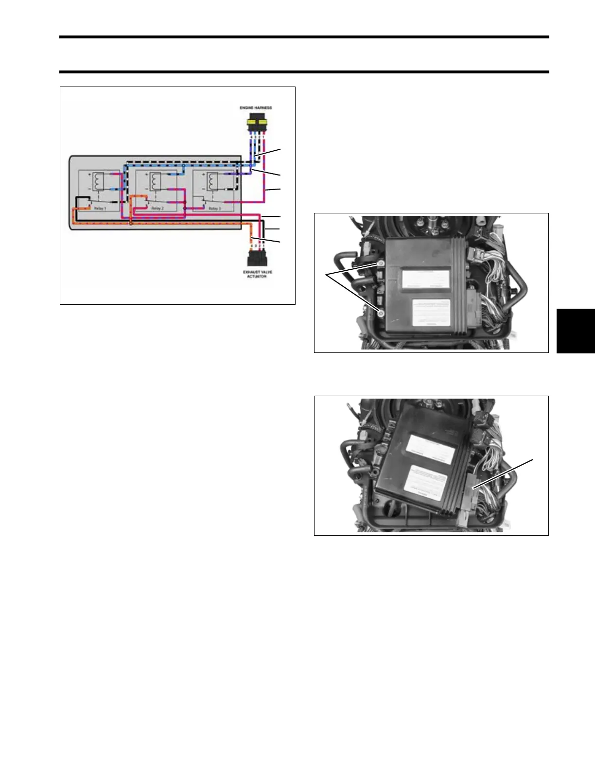
Operation
When the outboard is running, the fuel pump cir-
cuit (purple/black wire) provides 12V to activate
relay 3. Relay 3 provides fused 12V (red/purple
wire) to relay 1 and relay 2.
The EMM controls the exhaust valve by grounding
the blue/black wire.
When the blue/black wire is NOT grounded, fused
12V is supplied to the exhaust valve actuator
through the orange/red wire and the actuator is
grounded through the black wire on relay 1.
When the blue/black wire IS grounded, relay 1
and relay 2 are activated. Relay 2 supplies fused
12V to the exhaust valve actuator through the red
wire and the actuator is grounded through the
orange/red wire.
Use the Evinrude Diagnostic Software program for
“static” test of actuator motor.
EMM SERVICING
Removal
Disconnect exhaust pressure hose and cooling
hoses from EMM.
Disconnect J1-A and J1-B connectors.
Remove two EMM retaining screws. Lift EMM up
and to the port side.
Disconnect J2 connector.
Exhaust Valve Relay Module Diagram
1. Purple/Black wire
2. Red/Purple wire
3. Blue/Black wire
4. Black wire
5. Orange/Red wire
6. Red wire
005429
3
1
2
6
4
5
1. EMM mounting screws 005375
1. J2 Connector 005376
1
1