310
GEARCASE
REMOVAL AND INSTALLATION
Apply Gel-Seal II to gearcase mating surface pads
on exhaust housing. Slide the gearcase into
place, making sure:
• Driveshaft engages the crankshaft.
• Water tube enters the water pump.
• Lower inner exhaust housing installs correctly.
• Shift rod does not turn and is positioned prop-
erly in shift shaft connection area.
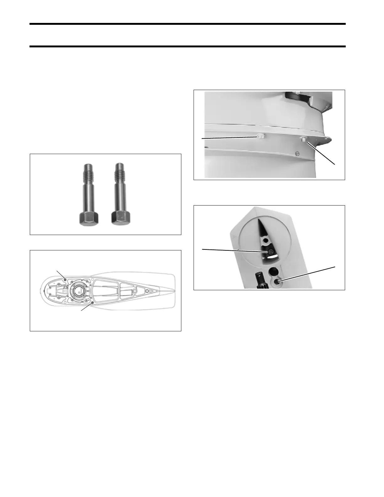
Use Gearcase Alignment Kit, P/N 5007231, to
accurately align gearcase housing to exhaust
housing. Position alignment bolts (2) as indicated.
IMPORTANT: Remove and replace alignment
screws with appropriate 3/8 in. mounting screws
after all other gearcase mounting screws are
installed and tightened.
Apply Gasket Sealing Compound to threads of the
gearcase retaining screws. Torque the screws:
• 3/8 in. screws – 26 to 28 ft. lbs. (35 to 38 N·m)
• 7/16 in. screws – 40 to 50 ft. lbs. (54 to 68 N·m)
Apply Gasket Sealing Compound to threads of the
trim tab screw. Install gasket on “M”-type gear-
cases. Install and align the trim tab (cover on “L”-
type) with the index marks noted prior to disas-
sembly. Torque the trim tab screw to 35 to 40 ft.
Alignment Bolt(s) 005401
1. Position of alignment bolts (2) 005402
1
1
1. Alignment screw
2. 3/8 in. screw
005403
1. 7/16 in. screw
2. 3/8 in screw
COA3139
1
2
1
2