3
Chapter 2
Controls
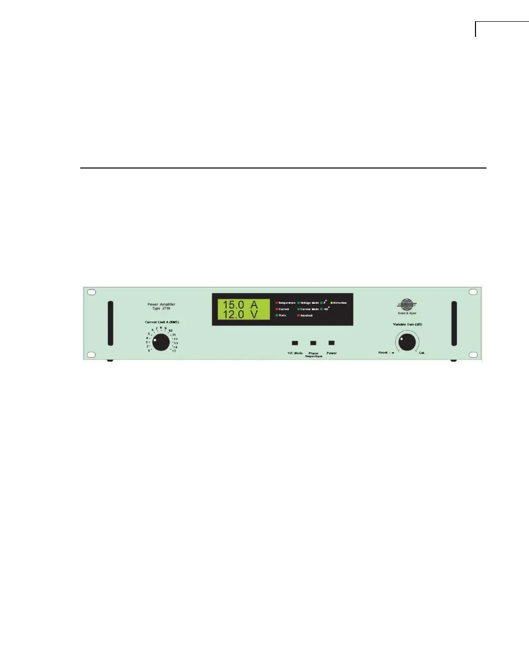
Front Panel
Fig.2.1 Front panel of Type 2719
Current Limit A (RMS): A single-turn potentiometer for limiting RMS current output.
Display: The display shows output AC current and voltage on a LCD display.
• The Temperature LED indicator lights red if the Power MOS Output Transistors overheat.
The amplifier then shuts-down
• The Current LED indicator lights red when output current to the load is exceeding the Cur-
rent Limit value set. The amplifier then shuts-down
• The State LED indicator lights green when the amplifier power is switched On
• The Voltage or Current Mode LED indicator lights green showing the output mode
• The Interlock LED indicator lights red when the interlock circuit is activated
• The 0° or 180° LED indicator lights green indicating phase shift from input to output
• The Distortion LED indicator lights yellow when output voltage or current clipping occurs
V/C Mode: Select feedback and output impedance modes. The positions are:
Voltage Mode: Provides constant voltage characteristics independent of changes of test
object on the exciter. Gives the best acceleration waveform and is therefore preferable for
most vibration tests.
Current Mode: Provides constant current characteristics, keeping the generated force inde-
pendent of changes of test object.

 Loading...


