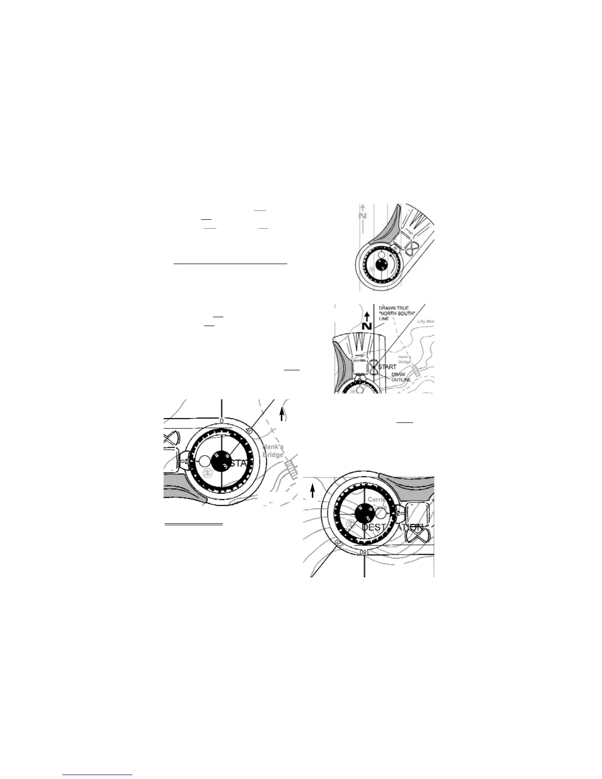
6. Rotate azimuth ring until blue orienting circle points to the
map’s true
north. (Fig 18)
· Align blue
line in vial and red lines on graduated dial with
drawn true north-south lines.
7. Read bearing.
6.3 Protractor And Centering Template
Use the centering template and the protractor to determine a map
bearing.
1. On the map, place a "point" at a starting position and an "X" at a destination.
2. Draw a bearing line connecting both marks.
3. Determine true north from the map’s legend.
4. Draw a true north-south line through the "point".
5. Place the centering template directly over the point".
6. Draw an outline around the "point". (Fig 19)
6.3.a -- 0° to 180° Map Bearing
1. With 0° on the protractor pointing north
, position
center of needle disk within the outline.
2. Using the 0° to 180° scale, read bearing where
the bearing line intersects the protractor. (Fig 20)
6.3.b -- 181° to 360° Map Bearing
1. With 0° on protractor pointing south
,
position center of needle disk within the
outline.
2. Using the 181° to 360° scale, read bearing
where the bearing line intersects the
protractor. (Fig 21)
7 – Triangulation
Determine field bearings to three visible landmarks
and plot them as map bearings. The
intersection of the bearing lines indicate your
approximate position. A landmark can be a
mountain peak, a cliff, or any visible object
displayed on your map.
8
Figure 18
Figure 19
Figure 20
Figure 21
N
N