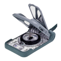
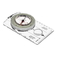
9. Keeping clear base stationary on the map,
rotate azimuth ring until blue orienting circle
points in a northerly direction, and the red lines
on graduated circle are aligned with the drawn
true north-south lines. (Fig 21)
10.Read bearing from the green
scale in magnified
index lens. (Fig 21)
If using a map other than a USGS or BLM map,
check that the map’s margin is aligned to true
north. If not aligned, it is necessary to draw true
north-south lines from the true north indicator
(indicated by an arrow with an "N" or a star).
Then, find map bearing.
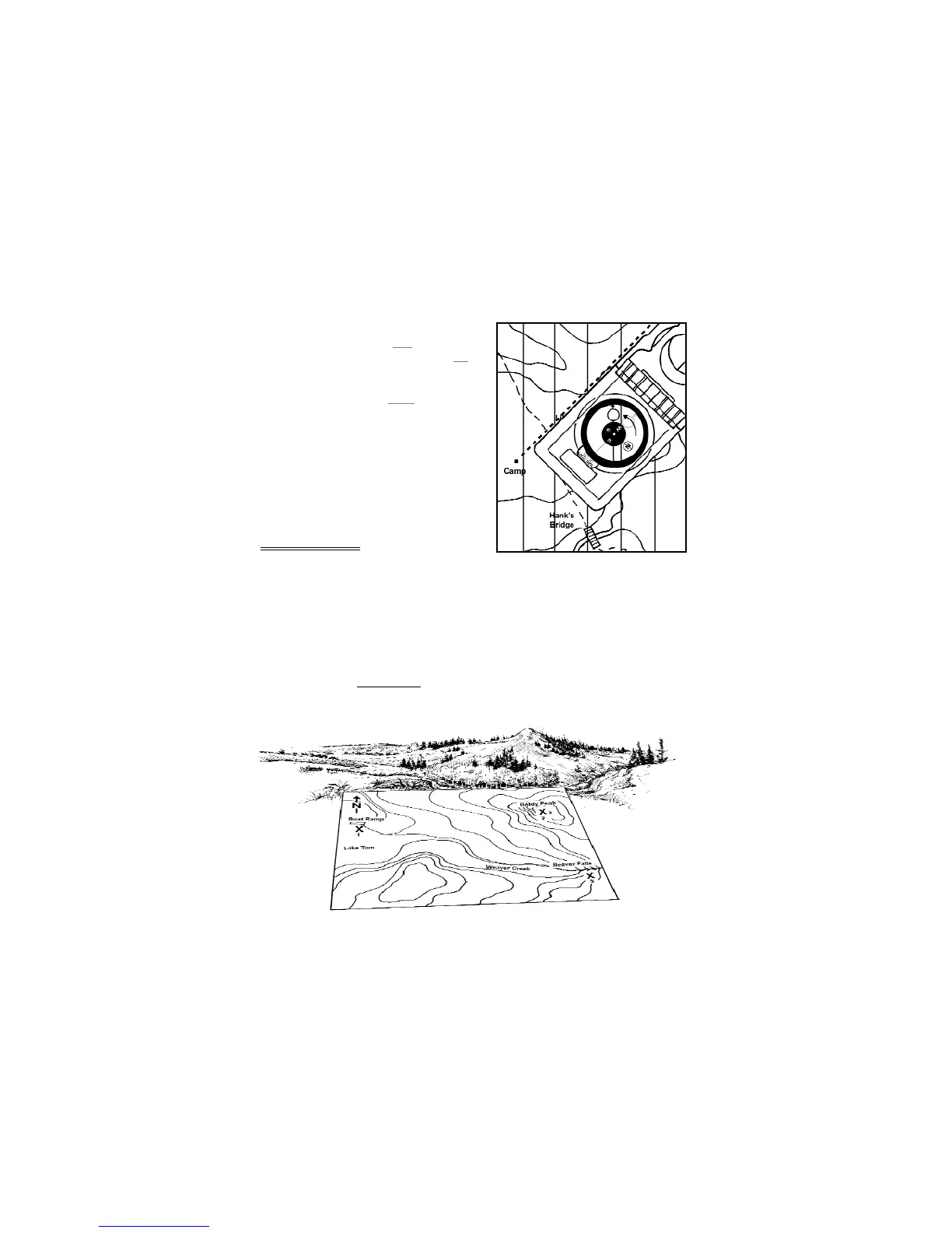
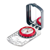
8 -- Triangulation
In this section, you will determine field bearings to
three visible landmarks and plot them as map bearings.
The intersection of the bearing lines indicate your approximate position. A landmark can be a
mountain peak, a cliff, or any visible object displayed on your map. The following example uses a
USGS 7.5 minute topo-map, and forward mirror sighting for bearing determination.
1. Adjust for magnetic declination.
2. Find three prominent landmarks in the field.
3. Orient the map to true north.
· See Section 7.1, Map Alignment
, for help.
4. Find all three landmarks on the map, place an ‘X’ at the positions and label them ‘1’, ‘2’ & ‘3’.
(Fig 22)
Figure 21
Figure 22
12