10
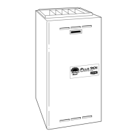
RTV
PAM
A93081
Fig. 12 -- Gasket on Collector Box
Step 6 — Servicing Hot Surface Igniter
The igniter does NOT require annual inspection. Check igniter
resistance before removal.
1. Turn off gas and electrical supplies to furnace.
2. Remove main furnace door.
3. Disconnect igniter wire connection.
4. Check igniter resistance. Igniter resistance is affect by tem-
perature. Only check resistance when the igniter is at room
temperature.
d. Using an ohm meter, check resistance across both ig-
niter leads in connector.
e. Cold reading should be between 40 ohms and 70 ohms.
5. Remove igniter assembly.
BURN HAZARD
Failure to follow this caution may result in minor personal
injury.
Allow igniter to cool before removal. Normal operating
temperatures exceed 2000°F.
CAUTION
!
a. Remove burner box cover.
b. Remove igniter wires from slot in manifold grommet.
(See Fig. 7.)
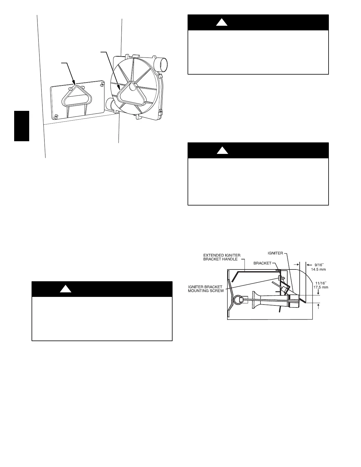
c. Using a 1/4 in. driver, remove the single screw securing
the igniter bracket to the burner box bracket (See Fig.
13.) and carefully withdraw the igniter and bracket as-
sembly through the front of the burner box without
striking the igniter on surrounding parts. Note that the
igniter bracket has a handle that extends to the front of
the burner box to aid in handling (See Fig. 13.).
d. Inspect igniter for signs of damage or failure.
UNIT DAMAGE HAZARD
Failure to follow this caution may result in premature failure
of the igniter.
The igniter is fragile. DO NOT allow it to hit the side of the
burner box parts while removing or replacing it.
CAUTION
!
e. If replacement is required, replace igniter on igniter
bracket and then install assembly to burner box to avoid
damage to the igniter.
6. To replace igniter and bracket assembly, reverse items 5a
through 5d.
7. Reconnect igniter wire connection and insert the igniter
wires in the slot in the manifold grommet, dressing the ig-
niter wires to ensure there is no tension on the igniter itself.
(See Fig. 7.)
ELECTRICAL SHOCK HAZARD
Failure to follow this warning could result in electrical shock,
personal injury, or death.
Igniter wires must be securely placed in slot in manifold
grommet or else they could become pinched or severed and
electrically shorted.
!
WARNING
8. Reinstall burner box cover.
9. Turn on gas and electrical supplies to furnace.
10. Verify igniter operation by initiating furnace control board
self-test feature or by cycling thermostat.
11. Replace main furnace door.
A05075
Fig. 13 -- Igniter Bracket
352AAV
 Loading...