5
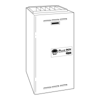
FILTER
RETAINER
FILTER
IN FURNACE
WASHABLE FILTER OR
DISPOSABLE MEDIA
FILTER IN FILTER CABINET
A08589
Fig. 4 -- Filter Installed for Side Inlet
COLLECTOR BOX
TUBE (PINK)
COLLECTOR BOX
TUBE (GREEN)
INDUCER HOUSING
(MOLDED) DRAIN
TUBE (BEHIND
COLLECTOR BOX
DRAIN TUBE)
COLLECTOR BOX
DRAIN TUBE (BLUE)
FIELD-INSTALLED
FACTORY-SUPPLIED
DRAIN TUBE
COUPLING (LEFT
DRAIN OPTION)
FIELD-INSTALLED
FACTORY-SUPPLIED
DRAIN TUBE
FIELD-INSTALLED
FACTORY-SUPPLIED
1
⁄
2
-IN. CPVC STREET
ELBOWS (2) FOR
LEFT DRAIN OPTION
FIELD-INSTALLED
FACTORY-SUPPLIED
DRAIN TUBE
COUPLING (RIGHT
DRAIN OPTION)
CAP
COLLECTOR BOX
DRAIN TUBE (BLUE
& WHITE STRIPED)
PLUG
CONDENSATE
TRAP
A01030
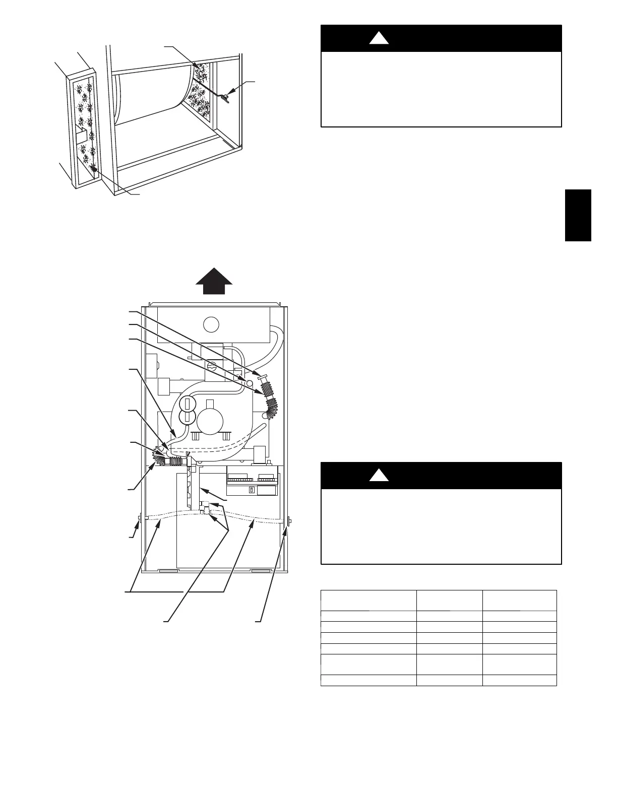
Fig. 5 -- Factory--Shipped Upflow Tube Configuration
(Shown with Blower Access Panel Removed)
UNIT DAMAGE HAZARD
Failure to follow this caution may result in noise or furnace
component failure.
The blower wheel should not be dropped or bent as balance
will be affected.
CAUTION
!
g. Clean wheel per instructions on degreaser cleaner. Do not
get degreaser in motor.
9. Reassemble motor and blower wheel by reversing items 8b
through 8f. Ensure wheel is positioned for proper rotation.
Tighten setscrew to between 140--160 in.--lb torque.
NOTE: Be sure to attach ground wire to blower housing.
10. Reinstall blower assembly in furnace.
11. Reinstall control box, transformer, and door switch as-
sembly on blower shelf.
12. Reinstall condensate trap and tubing if previously removed.
a. Reinstall condensate trap in hole in blower shelf.
b. Connect condensate trap drain tubes. See Fig. 5 or tubing
diagram on main furnace door for proper tube location.
(1.) Connect 1 tube (blue or blue and white striped) from
collector box.
(2.) Connect 1 tube (violet or unmarked) from inducer
housing.
(3.) Connect 1 tube (relief port, green or pink) from col-
lector box.
NOTE: Ensure tubes are not kinked or pinched, as this will affect
operation.
c. Connect field drain to condensate trap.
13. Reconnect wires. Refer to furnace wiring diagram and con-
nect thermostat leads if previously disconnected. (See Fig.
16.)
NOTE: Refer to Table 3 for motor speed lead reconnection if
leads were not identified before disconnection.
UNIT DAMAGE HAZARD
Failure to adjust the heating speed may shorten heat exchanger
life.
Heating air speed selection MUST be adjusted to provide
proper temperature rise as specified on the rating plate.
CAUTION
!
Table 3 – Speed Selection
COLOR SPEED
FACTORY
ATTACHED TO
White Common Com
Black High Cool
Yellow Medium High Spare
Orange{ Medium H i g h --- G a s H e a t
Blue Medium Low
S p a r e / H i g h --- G a s
Heat
Red Low* L o w --- G a s H e a t
*Continuous blower speed.
{Available on 5---speed blowers only.
352AAV
 Loading...