9
PLUG
CAP
COLLECTOR BOX
DRAIN TUBE (BLUE &
WHITE STRIPED)
INDUCER HOUSING
(MOLDED) DRAIN
UBE (BEHIND
COLLECTOR BOX
DRAIN TUBE)
COLLECTOR BOX
TUBE (PINK)
COLLECTOR BOX
DRAIN TUBE (BLUE)
COLLECTOR BOX
TUBE (GREEN
ROUTES BEHIND
INDUCER)
FIELD-INSTALLED
FACTORY-SUPPLIED
DRAIN TUBE
COUPLING (LEFT
DRAIN OPTION)
FIELD-INSTALLED
FACTORY-
SUPPLIED
DRAIN TUBE
FIELD-INSTALLED
FACTORY-
SUPPLIED
½ - IN. CPVC STREET
ELBOWS (2) FOR
LEFT DRAIN OPTION
FIELD- INSTALLED
FACTORY-
SUPPLIED
DRAIN TUBE
COUPLING (LEFT
DRAIN OPTION)
CONDENSATE
A07274
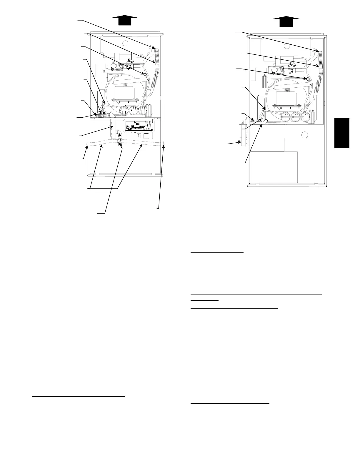
Fig. 7 -- Factory --Shipped Trap Location
(Shown with Blower Access Panel Removed)
1. Collector Box Drain Tube
Connect collector box d rain tube (blue label) to
condensate trap.
NOTE:On17--1/2--in.(444.5mm)widefurnaces ONLY, cut
tube between corrugated sections to prevent kinks.
2. Inducer Housing Drain Tube
a. Remove and discard LOWER (molded) inducer housing
draintubewhich was previously connected tocondensate
trap.
b. Use inducer housing drain extension tube (violet label
and factory--supplied in loose parts bag) to connect
LOWER inducer housing drain connection to
condensate trap.
c. Determine appropriate length, then cut and connect tube.
d. Clamp tube to prevent any condensate leakage.
3. Relief Port Tube
a. Connect relief port tube (green label) to condensate trap.
b. Extend this tube (if required) by splicing to small
diameter tube (factory --supplied in loose parts bag).
c. Determine appropriate length, then cut and connect tube.
Condensate Trap Field Drain
Attachment
Refer to Condensate Drain section for recommendations and
procedures.
PLUG
CAP
COLLECTOR BOX
DRAIN TUBE (BLUE &
WHITE STRIPED)
INDUCER HOUSING
(MOLDED) DRAIN
TUBE (VIOLET)
COLLECTOR BOX
TUBE (PINK)
COLLECTOR BOX
DRAIN TUBE (BLUE)
COLLECTOR BOX
TUBE (GREEN)
CONDENSATE
A07281
Fig. 8 -- Alternate Trap Location
Pressure Switch Tubing
The LOWER collector bo x pressure tube (pink label) is factory
connected to the pressure switch and should not require any
modification.
NOTE:SeeFig.7or8ortuberoutinglabelonmainfurnace
door to check for proper connections.
Upper Collector Box and Inducer Housing (Unused)
Drain
Connections
Upper Collector Box Drain
Connection
Attached to the UPPE R collector bo x drain connection is a
factory--installed corrugated, plugged tube (blue and white
striped label). This tube is plugged to prevent condensate leakage
in this application. Ensure this tube is plugged.
NOTE:SeeFig.7or8ortuberoutinglabelonmainfurnace
door to check for proper connections.
Upper Inducer Housing Drain
Connection
Attached to the UPP E R (unused) inducer h ou sing drain
connection is a cap and clamp. This cap is used to prevent
condensate leakage in this application. Ensure this connection is
capped.
NOTE:SeeFig.7or8ortuberoutinglabelonmainfurnace
door to check for proper connections.
Condensate Trap Freeze Pr
otection
Refer to Condensate Drain Protection section for
recommendations and procedures.
355CAV



 To Next Page