22
Heat Anticipator Settings —
Set heat anticipator settings at 0.14 amp for the first stage
and 0.14 amp for second−stage heating, when available.
Low Ambient Control (Factory Option)
If the unit comes with Electro−Mechanical (EM) control,
then no adjustment is necessary.
If the unit comes with the RTU Open controller option,
then refer to its installation control manual for details on
adjusting “Cooling Lock−Out” setting and configure for
your specific job requirements.
Variable Frequency Drive (VFD) 2−Speed Indoor
Fan Motor System (Factory Option)
For details on operating 581J 2 stage cooling units
equipped with the factory−installed Variable Frequency
Drive (VFD) 2−Speed Indoor Fan Motor System option,
refer to the Variable Frequency Drive (VFD) installation,
Setup & Troubleshooting Supplement.
EconoMi$er X − Ultra Low Leak Economizer
(Factory Option)
For details on operating 581J 2 stage cooling units equipped
with a factory−installed EconoMi$er X, refer to
Factory−Installed Economizers for 580J/558J/581J/551J/
549J/582J/559J/547J Rooftop Units, 3 to 27.5 Nominal Tons.
Economizer Supplement Related to California Title 24.
Perfect Humidityt System Control Connections
Perfect Humidity System − Space RH Controller —
NOTE: The Perfect Humidity system is a
factory−installed option which is only available for units
equipped with belt−drive motors.
The Perfect Humidity dehumidification system requires a
field−supplied and −installed space relative humidity
control device. This device may be a separate humidistat
control (contact closes on rise in space RH above control
setpoint) or a combination thermostat−humidistat control
device with isolated contact set for dehumidification
control. The humidistat is normally used in applications
where a temperature control is already provided (such as a
third−party Building Management System).
To connect a field−supplied humidistat:
1. Route the humidistat 2−conductor cable (field−sup-
plied) through the hole provided in the unit corner
post.
2. Feed wires through the raceway built into the corner
post (see Fig. 32) to the 24−v barrier located on the
left side of the control box. The raceway provides the
UL−required clearance between high−voltage and
low−voltage wiring.
3. Use wire nuts to connect humidistat cable to the leads
in the low–voltage wiring (as shown in Fig. 33), con-
necting PKN to PNK and PNK/BLK to PNK/BLK.
Refer to the instructions for the field−supplied hu-
midistat for more information.
To connect a field−installed programmable thermidistat:
1. Route the programmable thermidistat multi−conduct-
or cable (field−supplied) through the hole provided in
the unit corner post.
2. Feed wires through the raceway build into the corner
post (see Fig. 32) to the 24−v barrier located on the
left side of the control box. The raceway provides the
UL−required clearance between high−voltage and
low−voltage wiring.
3. The programmable thermidistat has dry contacts at
terminals D1 and D2 for dehumidification operation
(see Fig. 34). The dry contacts must be wired between
CTB terminal R and the PNK/BLK lead to the LTLO
switch with field−supplied wire nuts. Refer to the
installation instructions included with the
programmable thermidistat device for more
information.
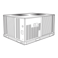
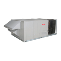
581J
 Loading...