SG-619AHB-01: Service Manual
Manufacturer reserves the right to change, at any time, specifications and designs without notice and without obligations.
7
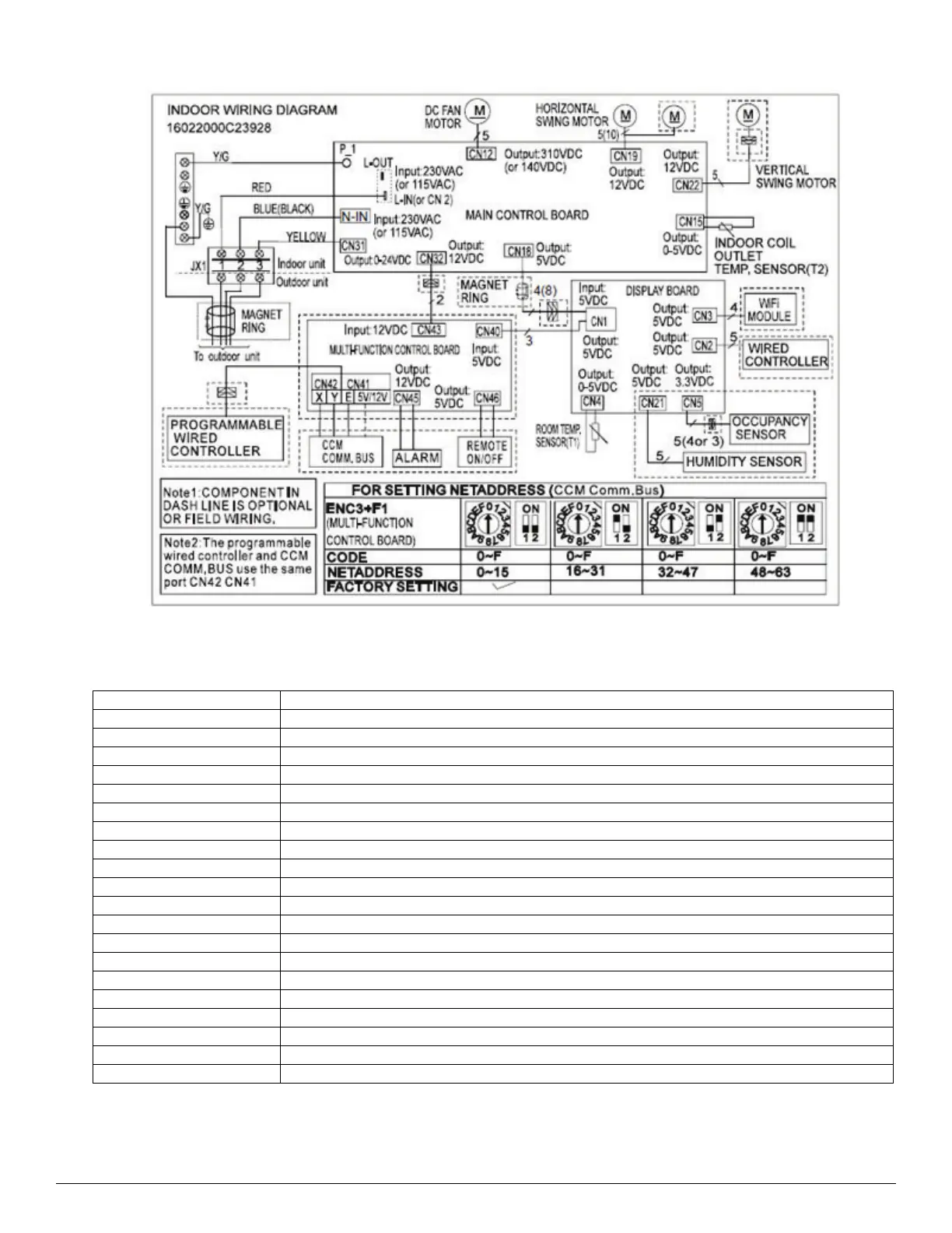
WIRING DIAGRAM
Fig. 6 —Wiring Diagram (All Sizes) 115 and 208/230))
Table 6 — Wiring Diagram (All Sizes) 115 and 208/230))
CODE PART NAME
CN3 Earth: connect to Ground
CN1 N_in: connect to N-Line (100-130V AC input)
CN2 L_in: connect to L-line (100-130V AC input)
CN16 S: connect to indoor unit
CN60 Connect to 4 way valve, 100-130V AC when is on
CN17 Connect to compressor heater, 100-130V when AC is on
CN 15 Connect to chassis heater, 100-130V AC when is on
CN25 Connect to AC fan
CN6 Used for testing
CN21 Connect to pipe temperature sensor T3, ambient temperature sensor T4, exhaust temperature sensor TP
CN7 Connect to DC Fan
CN31 Connect to Electric Expansion Valve
IPM 501 IPM for DC Fan
CN28 Connect to compressor
CN29 OV AC (standby)
CN30 10-230V AC (standby)
IPM 1 IPM for compressor
BRI Bridge
CN4_2 Connect to Reactor
CN4_3
 Loading...