10 Specifications subject to change without notice. SM619PHA-03
Sizes 18K to 24K
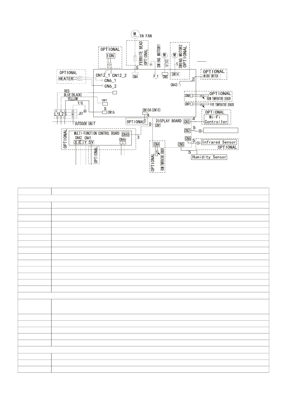
Fig. 6 — Wiring Diagram - Sizes 18K and 24K
CODE PART NAME
MAIN BOARD
S (Cn16) Output:0-24VDC Communication port to outdoor
N(CN11) Input:230VAC High Voltage N line from outdoor
L-IN (CN2) Input:230VAC High Voltage L line from outdoor
CN 6 Output:230VAC High Voltage Heater port (optional)
CN 12 Output:230V High Voltage Ion port (optional)
CN 4 Output:310VDC High Voltage Indoor DC fan
P_1 Output:0V Ground line welding on PCB
CN 5 Output:12VDC Swing motor 1
CN 14 Output:12VDC Swing motor2 (optional)
CN 43 Output:0-5VDC Micro switch (optional)
CN 44 Output:12VDC Plasma port (optional)
CN 8 Output:12VDC Room temperature sensor (optional)
CN 9 Output:12VDC Pipe temperature sensor
CN10A(CN10) Output:5VDC Connect to display board
DISPLAY BOARD
CN 1
Input:5VDC
4 wires connect to main board
3 wires connect to multi-function control board
CN 3 Output:5VDC Wi-Fi controller (optional)
CN 2 Output:5VDC Wire controller (optional)
CN 6 Output:3.3VDC Infrared sensor (operational)
CN 5 Output:5VDC Humidity sensor
CN 4 Output:12VDC Room temperature sensor (optional)
MULTI-FUNCTION CONTROL BOARD
CN42&CN41 Output:5VDC To CCM Comm. Bus or 485 Wire-controller
CN40 Input:5VDC Connect to display board
CN 46 Output:5VDC To Remote Switch
N
CN11
L- IN
CN 2
INDOOR UNIT
To Remote Switch
To CCM Comm.Bus or
485 Wire-controller