Do you have a question about the Bryant Base Series and is the answer not in the manual?
| Brand | Bryant |
|---|---|
| Model | Base Series |
| Category | Air Conditioner |
| Language | English |
Explains how to interpret model numbers for AC and heat pumps.
Details the format and meaning of serial numbers for unit identification.
Highlights critical hazards related to unit operation and safety.
Provides an overview of the document's purpose and scope.
General guidelines for installing units, including new construction and retrofits.
Specific installation requirements for new residential construction.
Guidelines for converting R22 systems to Puron refrigerant.
Special considerations for units installed in coastal environments.
Lists accessories required for specific AC applications.
Lists accessories required for specific heat pump applications.
Explains the function of the crankcase heater for compressor protection.
Describes the evaporator freeze thermostat for preventing coil freezing.
Details the isolation relay's role in heat pump low-ambient operation.
Explains the low-ambient pressure switch for controlling fan speed.
Describes the outdoor air temperature sensor for thermostat integration.
Explains the TXV's function in metering refrigerant flow.
Illustrates baffle assembly for low-ambient cooling.
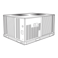
Describes the different cabinet designs for units.
Visual representation of the different unit cabinet designs.
Steps for removing the top cover on specific unit tiers.
Instructions for removing the fan motor assembly.
Information about the control box cover on base products.
Steps for removing the top cover on base product units.
Instructions for removing the fan motor assembly on base products.
Shows the locations of various labels on the unit.
Critical warning about electrical shock hazards.
Guidelines for using aluminum wire in electrical connections.
Explains the function and troubleshooting of the contactor.
Details the function and testing of capacitors.
Explains the low-pressure switch function in AC systems.
Details the high-pressure switch function in AC and HP systems.
Describes the loss of charge switch specific to heat pumps.
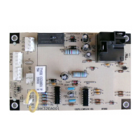
Specific defrost control board for Legacy Series heat pumps.
Operational sequence for cooling mode with this control.
Operational sequence for heating mode with this control.
Explains the defrost cycle initiation and termination.
Describes the Quiet Shift feature for noise reduction.
Explains the compressor delay feature.
Operational sequence for this control board.
Details the defrost cycle sequence.
Procedure for initiating a forced defrost.
Explains the Quiet Shift-2 feature for noise reduction.
Details ECM fan motor operation and troubleshooting.
Explains PSC fan motor operation and maintenance.
Critical warning about electrical shock hazards.
Information on the compressor electrical plug.
Description of low-voltage terminal designations.
Illustration of gas flow within a scroll compressor.
Diagram showing refrigerant flow in a scroll compressor.
Important safety cautions regarding compressor handling.
Key characteristics of LG scroll compressors.
Explains the internal motor overload protection system.
Details the vacuum protection feature in LG scroll compressors.
Describes the internal pressure relief mechanism.
Explains the device for minimizing shut-down noise.
Covers compressor discharge temperature protection.
Categorizes compressor failures into mechanical and electrical.
Discusses failures related to the compressor's mechanical components.
Critical warning about electrical shock hazards.
Describes the locked rotor failure mode.
Explains failures where the compressor runs but doesn't pump.
Part number for split post grommets.
Illustration of a suction line loop for noise reduction.
Identifies terminals and tests for single-phase motors.
Diagram for identifying compressor motor terminals.
Troubleshooting steps for open circuits in motor windings.
Critical warning about personal injury.
Warning about potential equipment damage.
Information on Puron refrigerant and safety.
Hazards related to Puron refrigerant operation.
Potential equipment damage from POE oil exposure.
Precautions for servicing units on synthetic roofing.
Steps to protect roofing material during service.
Specific procedures for brazing aluminum coils.
Warnings about service valve repair and pressure.
Diagram of a suction service valve.
Diagram of a front seating service valve.
Diagram of AccuRater components.
Steps to take if the reversing valve is found to be defective.
Diagram of the reversing valve in cooling/defrost mode.
Diagram of the reversing valve in heating mode.
Instructions for installing a liquid line filter drier in AC units.
Warnings about filter drier installation and damage.
Instructions for installing a liquid line filter drier in HP units.
Information on suction line filter driers for specific applications.
Illustration of AC liquid line filter drier installation.
Illustration of HP liquid line filter drier installation.
Steps for replacing the accumulator.
Safety caution regarding personal injury.
Diagram showing accumulator components.
Explains how the TXV operates to regulate refrigerant flow.
Guidelines for installing the TXV.
Warnings about TXV installation and equipment damage.
Hazard warning for equipment damage during TXV installation.
Procedure for installing TXV in older indoor coils.
Diagram showing correct sensing bulb placement.
Warnings regarding personal injury and environmental hazards.
Warning about equipment damage from POE oil exposure.
Warning about damage from buried refrigerant tubing.
Diagram showing typical TXV installation.
Methods for detecting refrigerant leaks in the system.
Illustration of electronic leak detection.
Hazards associated with using nitrogen for leak detection.
Illustration of bubble leak detection method.
Procedures for removing the unit coil.
Warning about fire hazard during tubing cuts.
Warning about premature corrosion failure of aluminum coils.
Diagram showing fin isolator location.
Illustration of using a braze shield.
Diagram showing fin isolator orientation.
Diagram of copper stub tube connection.
Warnings about personal injury and handling refrigerant.
Procedures for cleaning the system after compressor burnout.
Warning about damage from open systems and moisture.
Methods for evacuating the system.
Explanation of the deep vacuum method for evacuation.
Graph illustrating the deep vacuum process.
Diagram of the triple evacuation method.
Initial steps for diagnosing system issues using superheat.
Troubleshooting low superheat with specific pressure conditions.
Troubleshooting high suction pressure issues.
Diagnosing high superheat under specific pressure conditions.
Information needed for pseudo evaporator superheat calculation.
Diagram of tube fitting geometry.
Table showing equivalent feet for tube fittings.
Diagram for taking measurements for pseudo superheat.
Describes how the system operates in cooling and heating modes.
Details the operational sequence for cooling and heating.
Explains the status indicator lights on the control board.
Diagram of the control board layout.
Information on the amber status light for fault codes.
Explains the operation of the crankcase heater.
How the utility interface works with Evolution control.
Diagram of the utility interface wiring.
Utility interface wiring for non-communicating thermostats.
Low ambient cooling without a kit using Evolution control.
Low ambient cooling with standard thermostats.
How auto defrost adjusts interval times.
How defrost hold functions in non-communicating systems.
Methods for manually initiating a defrost cycle.
Describes the Quiet Shift-2 feature for noise reduction.
Connection details for Evolution control.
Connection details for non-communicating thermostats.
Functions controlled by the heat pump control board.
Wiring connections for Evolution and standard thermostats.
Explanation of compressor internal relief protection.
Diagnosing communication failures between units.
Importance of the correct model plug installation.
How pressure switches protect the unit.
Identifying control board failures.
Protection against low voltage conditions.
How the control senses compressor voltage.
Troubleshooting compressor thermal cutout issues.
How the control compares thermistor readings.
Default operations when a thermistor fails.
Resistance vs. temperature chart for thermistors.
How status codes are indicated by the amber LED.
Chart showing thermistor resistance values.
Guidelines for applying two-stage units.
Importance and function of the model plug.
Table detailing model plug numbers and resistances.
Airflow settings for specific furnace models.
Airflow settings for FV4C fan coils.
Requirements for operating below 55°F.
Low ambient cooling without a kit using Evolution control.
Explanation of defrost modes and timing.
Connection details for Evolution control.
Connection details for non-communicating thermostats.
Sequence of operation for cooling mode.
Sequence of operation for heating mode.
How the scroll compressor operates with unloading.
Noise reduction feature during defrost.
Defrost control for specific models.
Noise reduction feature for non-communicating systems.
Explanation of defrost control timing and termination.
Procedure for initiating a forced defrost.
Steps to troubleshoot ECM fan motor failures.
Unit time delays for various operations.
PWM output values for outdoor fan motors.
Components related to compressor discharge.
Function and troubleshooting of thermistors.
Role of the outdoor ambient thermistor.
Role of the outdoor coil thermistor.
Chart for thermistor resistance values.
Chart showing thermistor resistance values.
Discusses contactors and capacitors in the control box.
Information on incoming power connections and safety.
Critical warning about electrical shock.
Diagram of component mounting.
Specific troubleshooting for Evolution Series control boards.
Diagnosing communication failures.
Importance of correct model plug installation.
How pressure switches protect the unit.
Identifying control board failures.
Protection against brown-out conditions.
Diagram of a 2-stage control board.
How the control compares thermistor readings.
Default operations when a thermistor fails.
Diagram of OAT thermistor attachment.
Diagram of OCT thermistor attachment.
Outdoor operating ambient limits.
Airflow settings for ECM furnaces.
Airflow settings for variable speed furnaces.
Airflow settings for FV4C fan coils.
Requirements for operating below 55°F.
Explanation of defrost modes and timing.
Sequence of operation for cooling mode.
Sequence of operation for heating mode.
How the scroll compressor operates with unloading.
Noise reduction feature during defrost.
Defrost control for specific models.
Noise reduction feature for non-communicating systems.
Explanation of defrost control timing and termination.
Procedure for initiating a forced defrost.
Critical warning about electrical shock.
Warning about equipment damage during maintenance.
Special maintenance for harsh environments.
Procedure for cleaning the unit's coil.
Warning about coil fin damage.
Procedure for cleaning the fan motor and blade.
Troubleshooting steps for a non-running compressor.
Troubleshooting steps for cooling performance issues.
Troubleshooting steps for a non-running compressor in heating.
Troubleshooting steps for heating performance issues.
Troubleshooting steps for a non-running compressor in cooling.
Troubleshooting steps for cooling performance issues.