—
30
—
XV. ECONOMI$ER LEDs
The EconoMi$er control module has an LED for diagnostic
purposes. The flash code identification is shown in Table 16.
XVI. OPTIONAL HINGED ACCESS DOORS
When the hinged access doors option is ordered, the unit will
be provided with external and internal hinged access doors
to facilitate service.
Four external hinged access doors are provided on size 180-
240 units. Two external hinged doors are provided on
size 300 units. All external doors are provided with 2 large
1
/
4
turn latches with folding bail-type handles. (Compressor
access doors have one latch.) A single door is provided for
filter and drive access. One door is provided for control box
access. The control box access door is interlocked with the
non-fused disconnect which must be in the OFF position to
open the door. On size 180-240 units, two doors are provided
for access to the compressor compartment.
Two internal access doors are provided inside the filter/drive
access door. The filter access door (on the left) is secured by
2 small
1
/
4
turn latches with folding bail-type handles. This
door must be opened prior to opening the drive access door.
The drive access door is shipped with 2 sheet metal screws
holding the door closed. Upon initial opening of the door,
these screws may be removed and discarded. The door is
then held shut by the filter access door, which closes over it.
LEGEND AND NOTES FOR FIG. 38 AND 39
LEGEND
AHA —
Adjustable Heat Anticipator
BRK W/AT —
Breaks with Amp Turns
C —
Contactor, Compressor
CB —
Circuit Breaker
CC —
Cooling Compensator
CLO —
Compressor Lockout
COMP —
Compressor Motor
CR —
Control Relay
CT —
Current Transformer
DAT —
Discharge Air Thermistor
DM —
Damper Motor
DU —
Dummy Terminal
EC —
Enthalpy Control
EQUIP —
Equipment
FL —
Fuse Link
FLA —
Full Load Amps
FPT —
Freeze Protection Thermostat
FU —
Fuse
GND —
Ground
HC —
Heater Contactor
HPS —
High-Pressure Switch
HTR —
Heater
IFC —
Indoor-Fan Contactor
IFCB —
Indoor-Fan Circuit Breaker
IFM —
Indoor-Fan Motor
IFR —
Indoor-Fan Relay
L —
Light
LOR —
Lockout Relay
LPS —
Low-Pressure Switch
LS —
Limit Switch
NEC —
National Electrical Code
OAT —
Outdoor-Air Thermostat
OFC —
Outdoor-Fan Contactor
OFM —
Outdoor-Fan Motor
OP —
Overcurrent Protection
PL —
Plug Assembly
PRI —
Primary
TB —
Terminal Block
TC —
Thermostat Cooling
TH —
Thermostat Heating
TRAN —
Transformer
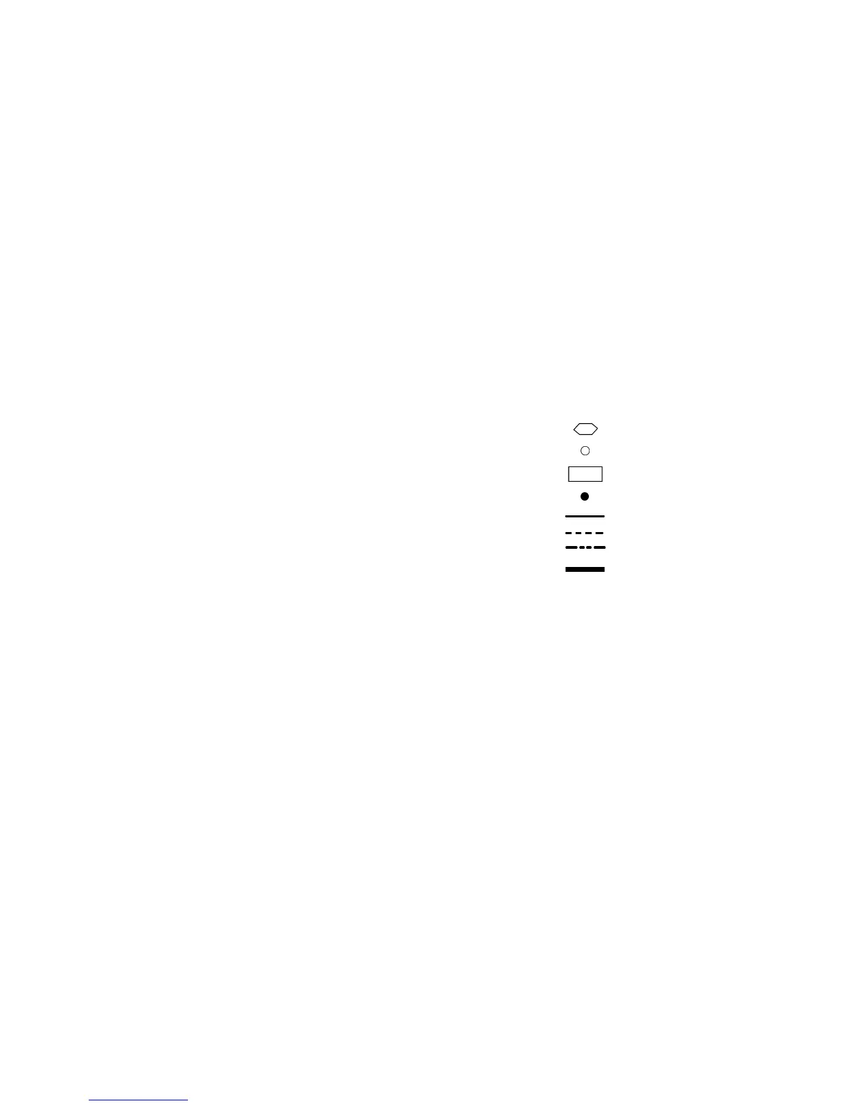
Terminal (Marked)
Terminal (Unmarked)
Terminal Block
Splice
Factory Wiring
Field Control Wiring
Option/Accessory Wiring
To indicate common potential
only; not to represent wiring.
NOTES:
1. Compressor and fan motor(s) thermally protected; 3-phase motors protected
against primary single-phasing conditions.
2. If any of the original wire furnished must be replaced, it must be replaced with
type 90 C wire or its equivalent.
3. TRAN1 is wired for 230 v operation. If unit is 208 v, disconnect the black wires
from the ORN TRAN wire and reconnect to the RED TRAN wire, apply wirenuts
to wires.
5. IFCB must trip amps is equal to or less than 140% FLA.
6. The CLO locks out the compressor to prevent short cycling on compressor over-
load and safety devices. Before replacing CLO, check these devices.
7. Jumpers are omitted when unit is equipped with EconoMi$er.
8. Number(s) indicates the line location of used contacts. A bracket over (2) num-
bers signifies a single-pole, double-throw contact. An underlined number sig-
nifies a normally closed contact. Plain (no line) number signifies a normally open
contact.