16
NOTE: Unit may be equipped with short test leads (pigtails) on
the field line connection points on contactor C or optional discon-
nect switch. These leads are for factory-run test purposes only; re-
move and discard before connecting field power wires to unit con-
nection points. Make field power connections directly to line con-
nection pressure lugs only.
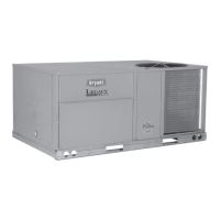
Fig. 26 — Power Wiring Connections
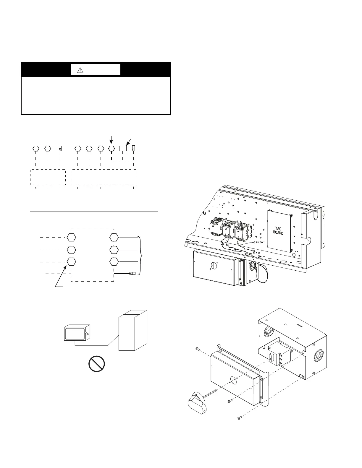
Fig. 27 — Disconnect Switch and Unit
UNITS WITH FACTORY-INSTALLED NON-FUSED DIS-
CONNECT
The factory-installed option non-fused disconnect (NFD) or
HACR switch is located in a weatherproof enclosure located un-
der the main control box. The manual switch handle and shaft are
shipped in the disconnect or HACR enclosure. Assemble the shaft
and handle to the switch at this point. Discard the factory test leads
(see Fig. 28).
Connect field power supply conductors to LINE side terminals
when the switch enclosure cover is removed to attach the handle.
Field-Install the NFD Shaft and Handle
1. Remove unit front panel (see Fig. 2).
2. Remove (3) hex screws on the NFD enclosure — (2) on the
face of the cover and (1) on the left side cover. See Fig. 28.
3. Remove the front cover of the NFD enclosure.
4. Make sure the NFD shipped from the factory is at OFF
position (the arrow on the black handle knob is at OFF).
5. Insert the shaft with the cross pin on the top of the shaft in
the horizontal position. See Fig. 29.
6. Measure from the tip of the shaft to the top surface of the
black pointer; the measurement should be 3.75 to 3.88 in.
(95 to 99 mm).
7. Tighten the locking screw to secure the shaft to the NFD.
8. Turn the handle to the OFF position with red arrow point-
ing at OFF.
9. Install the handle on to the painted cover horizontally with
the red arrow pointing to the left.
10. Secure the handle to the painted cover with (2) screws and
lock washers supplied.
11. Engaging the shaft into the handle socket, re-install (3)
hex screws on the NFD enclosure.
12. Re-install the unit front panel.
Fig. 28 — NFD Enclosure Location
Fig. 29 — NFD Handle and Shaft Assembly
WARNING
FIRE HAZARD
Failure to follow this warning could result in intermittent oper-
ation or performance satisfaction.
Do not connect aluminum wire between disconnect switch and
unit. Use only copper wire.
C
11 23
Disconnect
per
NEC
208/230-1-60
or
Disconnect
per
NEC
11 13 13 23
L1 L2 L3
TB
CIFC
Direct Drive IFM
208/230-3-60
460-3-60
575-3-60
Units Without Disconnect or HACR Option
Units With Disconnect or HACR Option
L1
L2
L3
2
4
6
1
5
Optional
Disconnect
Switch
Disconnect factory test leads; discard.
Factory
Wiring
1-ph Belt Drive IFM
3
Equip
GR Lug
Ground
(GR)
Ground
(GR)
Equip
GR Lug
Equip GR Lug
Ground
(GR)
3 Phase Only 3 Phase Only
COPPER
WIRE ONLY
ELECTRIC
DISCONNECT
SWITCH
ALUMINUM
WIRE

 Loading...