32
SYSTEM
SETUP
INSTALL 01/01/10 N/A
Display order = MM/DD/YY
Setting order = DD, MM, then YY.
UNITS DEG F F or C Sets economizer controller in degrees Fahrenheit or Celsius
EQUIPMENT CONV
Conventional or
HP
CONV = conventional;
HP O/B = Enable Heat Pump mode. Use AUX2 I for Heat Pump input
from thermostat or controller.
See Menu Note 7.
AUX2 IN W
SD/W or HP(O)/
HP(B)
In CONV mode:
SD + Enables configuration of shutdown (default);
W = Informs controller that system is in heating mode.
NOTE: If using 2-speed fan mode, ONV mode must be programmed
for W. Shutdown is not available in 2-speed fan mode. See Menu
Note 7.
In HP O/B mode:
HP(O) = energize heat pump on Cool (default);
HP(B) = energize heat pump on heat.
FAN SPEED 2 speed 1 speed/2 speed
Sets the economizer controller for operation of 1 speed or 2 speed
supply fan.
NOTE: 2-speed fan option also needs Heat (W1) programmed in AUX
2 In. See Menu Note 7.
FAN CFM 5000cfm
100 to 15000
cfm;
increment by
100
UNIT DESIGN AIRFLOW (CFM)
Enter only if using DCVAL ENA = AUTO
The value is on the nameplate label for the specific unit.
AUX1 OUT NONE
NONE
ERV
EXH2
SYS
Select OUTPUT for AUX1 O relay
• NONE = not configured (output is not used)
• ERV = Energy Recovery Ventilator
• EXH2 = second damper position relay closure for second exhaust
fan
• SYS = use output as an alarm signal
OCC INPUT
INPUT or
ALWAYS
OCCUPIED MODE BY EXTERNAL SIGNAL
When using a setback thermostat with occupancy out (24 vac), the 24
vac is input “INPUT” to the OCC terminal. If no occupancy output from
the thermostat then change program to “ALWAYS” OR add a jumper
from terminal R to OCC terminal.
FACTORY DEFAULT NO NO or YES
Resets all set points to factory defaults when set to YES. LCD
will
briefly flash YES and change to NO but all parameters will change to
the factory default values.
NOTE: RECHECK AUX2 IN and FANTYPE for required 2-speed
values.
ADVANCED
SETUP
MA LO SET 45
°
F
35 to 55°F;
Incremented by
1
0
SUPPLY AIR TEMPERATURE LOW LIMIT
Temperature to achieve Freeze Protection (close damper and alarm if
temperature falls below setup value).
FREEZE POS CLO CLO or MIN
FREEZE PROTECTION DAMPER POSITION
Damper position when freeze protection is active (closed or MIN
POS).
CO2 ZERO 0ppm
0 to 500 ppm;
Increment by 10
CO
2
ppm level to match CO
2
sensor start level.
CO2 SPAN 2000ppm
1000 to 3000
ppm; Increment
by 10
CO
2
ppm span to match CO
2
sensor.
STG3 DLY 2.0h
0 min, 5 min, 15
min, then 15 min
intervals. Up to 4
hrs or OFF
COOLING STAGE 3 DELAY
Delay after stage 2 cool has been active. Turns on 2
nd
stage of
cooling when economizer is 1
st
stage and mechanical cooling is 2
nd
stage. Allows three stages of cooling, 1 economizer and 2 mechanical.
OFF = no Stage 3 cooling
SD DMPR POS CLO CLO or OPN
Indicates shutdown signal from space thermostat or unitary controller.
When controller receives 24 Vac input on the SD terminal in
conventional mode, the OA damper will open if programmed for OPN
and OA damper will close if programmed for CLO. All other controls,
e.g., fans, etc. will shut off.
DA LO ALM 45°F (7°C)
35 to 65°F; (2 to
18°C)
Incremented by
5 deg.
Used for alarm for when the DA air temperature is too low. Set lower
range of alarm, below this temperature the alarm will show on the
display.
DA HI ALM 80°F (27°C)
70 to 180°F; (21
to 82°C)
Incremented by
5 deg.
Used for alarm for when the DA air temperature is too high. Set upper
range of alarm, above this temperature the alarm will show on the
display.
DCVCAL ENA MAN
MAN (manual)
AUTO
Turns on the DCV automatic control of the dampers. Resets
ventilation based on the RA, OA, and MA sensor conditions. Requires
all 3 RA, OA, and MA sensors.
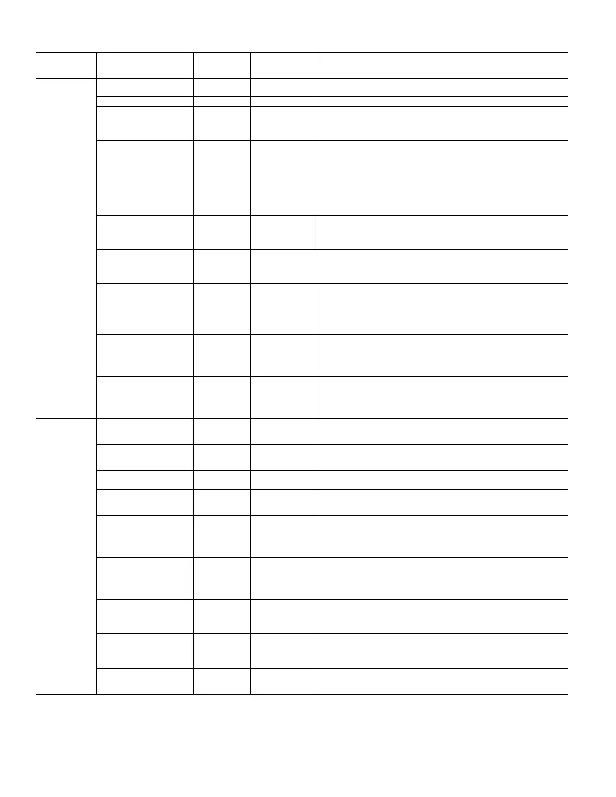
Table 11 — Menu Structure (cont)
MENU PARAMETER
PARAMETER
DEFAULT
VALUE
PARAMETER
RANGE AND
INCREMENT
NOTES
 Loading...