6
Table 6 — 569J*12-14D/E/F Physical Data
INSTALLATION
Jobsite Survey
Complete the following checks before installation.
1. Consult local building codes and the NEC (National Elec-
trical Code) ANSI/NFPA 70 for special installation
requirements.
2. Determine unit location (from project plans) or select unit
location.
3. Check for possible overhead obstructions which may
interfere with unit lifting or rigging.
Step 1 — Plan for Unit Location
The 569J units are designed and approved for outdoor installa-
tion only. Do not locate these units indoors. Do not add ducting
to unit fan system.
Select a location for the unit and its support system (pad, rails
or other) that provides for the minimum clearances required for
safety. This includes the clearance to combustible surfaces,
unit performance and service access below, around and above
unit as specified in unit drawings. See Fig. 4.
NOTE: Local codes may require different clearances than
specified in Fig. 4. It is the responsibility of installers to be
knowledgeable in local codes and to modify the recommended
clearances to satisfy local codes.
NOTE: Consider also the effect of adjacent units on airflow per-
formance and control box safety clearance.
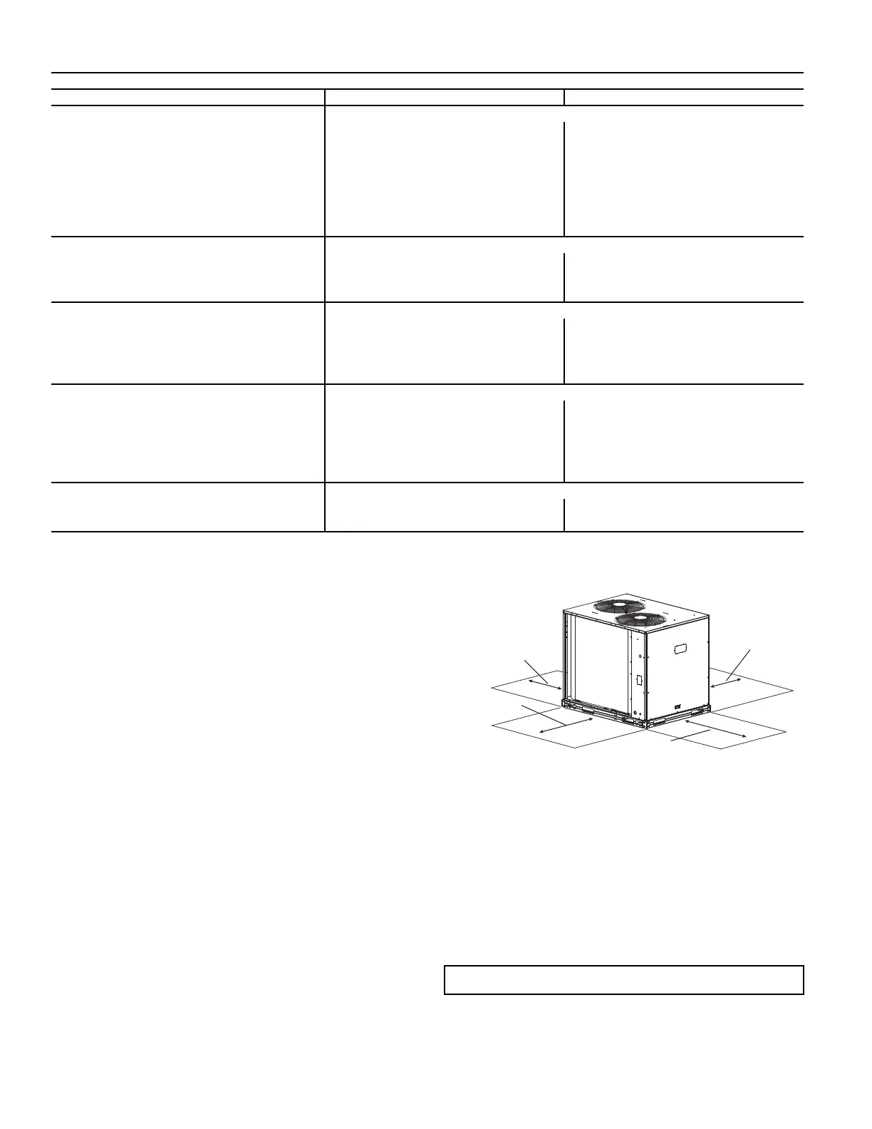
Fig. 4 — Service Clearance Dimensional Drawing
Do not install the outdoor unit in an area where fresh air supply
to the outdoor coil may be restricted or when recirculation
from the condenser fan discharge is possible. Do not locate the
unit in a well or next to high walls.
Evaluate the path and required line length for interconnecting
refrigeration piping, including suction riser requirements (out-
door unit above indoor unit), liquid line lift (outdoor unit be-
low indoor unit) and hot gas bypass line. Relocate sections to
minimize the length of interconnecting tubing.
Although unit is weatherproof, avoid locations that permit wa-
ter from higher level runoff and overhangs to fall onto the unit.
TWO CIRCUIT MODELS with RTPF – ROUND TUBE/PLATE FIN COIL DESIGN
569J*12D/E/F 569J*14D/E
Refrigeration System
# Circuits / # Comp. / Type 2 / 2 / Scroll 2 / 2 / Scroll
Refrigerant Type Puron
®
R-410A Puron R-410A
R-410A shipping charge A/B (lbs) 9.0 / 9.0 9.0 / 9.0
System charge w/ fan coil* 11.0 / 11.0 22.0 / 22.0
Metering device TXV TXV
High-press. Trip / Reset (psig) 630 / 505 630 / 505
Low-press. Trip / Reset (psig) 54 / 117 54 / 117
Compressor
Model (Qty) ZP51 (2) ZP67 (2)
Oil Charge A/B (oz) 42 / 42 56 / 56
Speed (rpm) 3500 / 2900 3500 / 2900
Condenser Coil
Material Al/Cu Al/Cu
Coil type RTPF RTPF
Rows / FPI 2 / 17 3 / 17
total face area (ft
2
) 25.1 31.8
Condenser fan / motor
Qty / Motor drive type 2 / direct 2 / direct
Motor HP / RPM
1
/
4
/ 1100
1
/
4
/ 1100
Fan diameter (in.) 22 22
Nominal Airflow (cfm) 6,000 6,000
Watts (total) 610 610
Piping Connections
Qty / Suction (in. ODS) 2 / 1
1
/
8
2 / 1
3
/
8
Qty / Liquid (in. ODS) 2 /
3
/
8
2 /
1
/
2
* Approximate system charge with about 25 ft piping of sizes indicated with matched 524J evaporator coil.
IMPORTANT: DO NOT BURY REFRIGERANT LINES.
REAR:
Min 18" (457 mm)
required for service
RIGHT:
Min 18" (457 mm)
required for service
LEFT:
Min 18" (457 mm)
required for service
FRONT:
42” (1067 mm)
required for service
NOTE: Observe requirements for 39" (914 mm) operating
clearance on either Left or Rear coil opening.

 Loading...