15
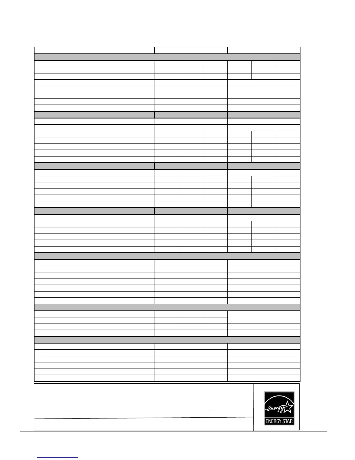
Table 6: Technical specifications
MULTI POSITIONS MODELS - SERIES 098
RATING AND PERFORMANCE
Firing rate (USGPH)* 0,50 0,60 0,70 0,50 0,60 0.70
Input (BTU/h)* 70 000 84 000 98 000 70 000 84 000 98 000
Maximum Heating capacity, (BTU/h)* 59 200 70 400 80 800 59 200 70 400 80 800
Heating temperature rise (Degr. F)*
Flue draft with chimney (inch of w.c.)
Overfire pressure w ith chimney (inch of w.c.)
Flue pressure w ith direct vent (inch of w.c.)
Overfire pressure w ith direct vent (inch of w.c.)
BECKETT BURNER; MODEL NX (Chim ne y or DV)
Burner tube insertion length (inches)
Head type
Nozzle (Delavan) 0.40 - 60A 0.50 60A 0.60 - 60A 0.40 - 60A 0.50 - 60A 0.60 - 60A
Minimum and Maximum pump pressure (PSIG)* 155 145 135 155 145 135
Head/Air setting 0,5 1,5 2,5 0,5 1,5 2,5
AFUE % (From CSA B212 standard and Canadian regulation)** 85.0 ‡ 84,2 81,9 85.0 ‡ 84,2 81,9
AFUE % (From ASHRAE 103 standard and US regulation)** 85.0 ‡ 83,9 81,9
85.0 ‡
83,9 81,9
RIELLO BURNER; MODEL 40-F3 (Chimney)
Burner tube insertion length (inches)
Nozzle (Delavan) 0.40 - 70A 0.50 - 70A 0.60 - 70A 0.40 - 70A 0.50 - 70A 0.60 - 70A
Minimum and Maximum pump pressure (PSIG)* 155 145 135 155 145 135
Combustion air adjustment (turbulator/damper) 0 / 1.5 0 / 2.5 1 / 3.5 0 / 1.5 0 / 2.5 1 / 3.5
AFUE % (From CSA B212 standard and Canadian regulation)** 85.0 ‡ 84,2 81,9 85.0 ‡ 84,2 81,9
AFUE % (From ASHRAE 103 standard and US regulation)** 85.0 ‡ 83,9 81,9
85.0 ‡
83,9 81,9
RIELLO BURNER; MODEL 40- BF3 (Dir ect vent DV)
Burner tube insertion length (inches)
Nozzle (Delavan) 0.40 - 70A 0.50 - 70A 0.60 - 70A 0.40 - 70A 0.50 - 70A 0.60 - 70A
Minimum and Maximum pump pressure (PSIG)* 155 145 135 155 145 135
Combustion air adjustment (turbulator/damper) 0 / 3.25 0 / 4 1 / 5.25 0 / 3.25 0 / 4 1 / 5.25
AFUE % (From CSA B212 standard and Canadian regulation)** 85.0 ‡ 84,2 81,9 85.0 ‡ 84,2 81,9
AFUE % (From ASHRAE 103 standard and US regulation)** 85.0 ‡ 83,9 81,9
85.0 ‡
83,9 81,9
ELECTRICAL SYSTEM
Volts - Hertz - Phase
Rated current (Amps)
Minimum ampacity for wire sizing (Amps)
Max. fuse size (Amps)
Control transformer (VA)
External control pow er available Heating (VA)
Cooling (VA)
BLOWER DATA
Heating blow er speed at 0.25" W.C. SP MED-LOW MED-HIGH HIGH
Heating blow er speed at 0.50" W.C. SP MED-LOW MED-HIGH HIGH
Motor (HP) / number of speeds
Blower size (diam. x width)
GENERAL INFORMATION
Overall dimensions (w idth x depth x height)
Supply air opening (width x depth)
Return air opening (width x depth)
Filter size (depth x hieght x thickness)
Shipping weight Lbs/Kg
Air conditioning, maximum output (tons) at 0.5 SP
-0.06 to -0.025 -0.06 to -0.025
-0.035 to +0.010
19'' x 19'' 19'' x 19''
+0.05 to +0.20 +0.05 to +0.20
+0.03 to +0.15
16.875'' x 20 1/8'' x 40 3/4'' 16.875'' x 20 1/8'' x 40 3/4''
UNITS WITH 1/3 HP PSC MOTOR UNITS WITH 1/2 HP ECM MOTOR
55 - 85 Degr. F 55 - 85 Degr. F
-0.035 to +0.010
+0.03 to +0.15
NX5 6L Q NX5 6L Q
1 3/4'' 1 3/4''
6 - Slot LQ head 6 - Slot LQ head
F3 WITH AIR INLET DAMPER F3 WITH AIR INLET DAMPER
2 3/4'' 2 3/4''
BF3 BF3
2 3/4'' 2 3/4''
115 - 60 - 1 115 - 60 - 1
15 15
10.3
13.7 12.2
12.2
40 40
40 40
30 30
See the ECM air flow table
1/3 HP / 4 speeds 1/2 HP / ECM
10'' x 8'' 10'' x 8''
2,5 3.0
20'' x 20'' 20'' x 20''
125 / 57 125 / 57
16'' x 19'' 16'' x 19''
* INPUT & OUTPUT ADJUSTMENT
Pump pressure can be adjusted to maintain proper firing rate. ‡ =
Increase pump pressure if flue gases temperature is under 400˚F
Adjust the total
flue gas temperature between 400˚F and 575˚F (330˚F and 505˚F net approximately)
Adjust fan speed for air temperature rise of 55˚ to 85˚F.
** AFUE value established after minimum 20 hours of o
eration.