16
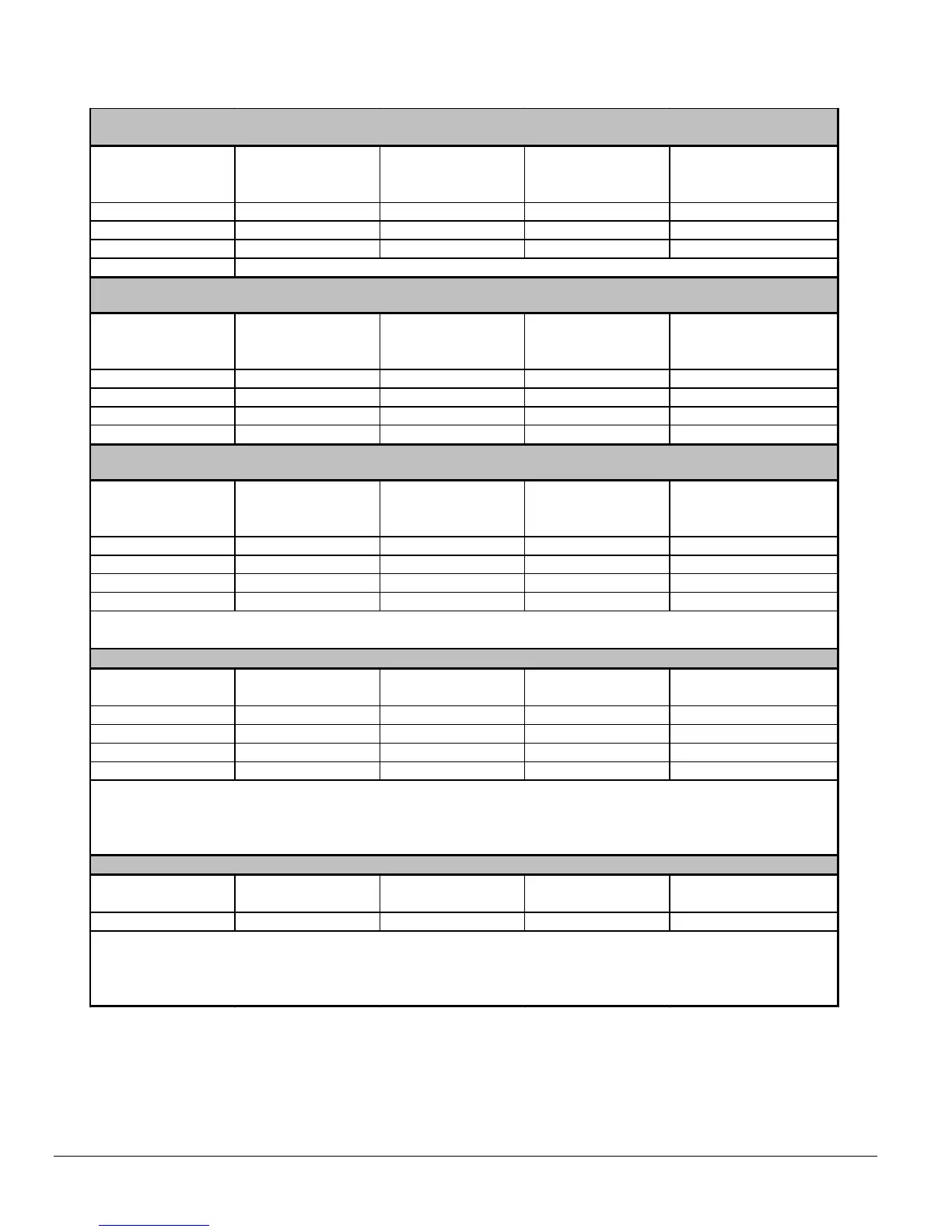
Table 7: Airflow data, models with 1/2 HP ECM motors
SW1- HEAT
DIP switch position
HEAT INPUT
(USGPH)
CFM with SW3-ADJ
DIP switch position A
CFM with SW3-ADJ
DIP switch position B
CFM with SW3-ADJ
DIP switch position C
A
(1=OFF, 2=OFF)
0,70 1260 1385 1135
B
(1=ON, 2=OFF)
0,60 1050 1155 945
C
(1=OFF, 2=ON)
0,50 850 935 765
D
(1=ON, 2=ON)
SW2- COOL
DIP switch position
A/C size
(TON)
CFM with SW3-ADJ
DIP switch position A
CFM with SW3-ADJ
DIP switch position B
CFM with SW3-ADJ
DIP switch position C
A
(1=OFF, 2=OFF)
3,0 900 1035 765
B
(1=ON, 2=OFF)
2,5 750 860 635
C
(1=OFF, 2=ON)
2,0 600 690 510
D
(1=ON, 2=ON)
1,5 450 515 380
SW2- COOL
DIP switch position
A/C size
(TON)
CFM with SW3-ADJ
DIP switch position A
CFM with SW3-ADJ
DIP switch position B
CFM with SW3-ADJ
DIP switch position C
A
(1=OFF, 2=OFF)
3,0 1200 1320 1080
B
(1=ON, 2=OFF)
2,5 1000 1100 900
C
(1=OFF, 2=ON)
2,0 800 880 720
D
(1=ON, 2=ON)
1,5 600 660 540
SW4- DELAY
DIP switch position
HEAT INPUT
(USGPH)
PreRun On-Delay
CFM Level - Time
ShortRun On-Delay
CFM Level - Time
Off-Delay
CFM Level - Time
A
(1=OFF, 2=OFF)
0,75 13% - 45 sec. 19% - 30 sec 38% - 3 min.
B
(1=ON, 2=OFF)
0,65 13% - 45 sec. 19% - 60 sec 38% - 3 min.
C
(1=OFF, 2=ON)
0,50 13% - 60 sec. 13% - 60 sec 38% - 3 min.
D
(1=ON, 2=ON)
All 13% - 30 sec. 100% - 30 sec 100% - 2 min.
No adjustment
required
A/C size
PreRun On-Delay
CFM Level - Time
ShortRun On-Delay
CFM Level - Time
Off-Delay
CFM Level - Time
- All No delay No delay 100% - 90 sec.
PreRun and ShortRun are the periods of time when the blower starts at very low CFM to minimize the
distribution of cool air in the system and then runs up to normal speed.
Off Delay is the time required to cool down the coil (heating mode) with low CFMs, to minimize cool draft
in the air distribution system.
DELAY PROFILE FOR COOLING OR HEAT PUMP HEATING MODE
PreRun and ShortRun are the periods of time when the blower starts at very low CFM to minimize the
distribution of cool air in the system and then runs up to normal speed.
Off Delay is the time required to cool down the heat exchanger with low CFMs, to minimize cool draft in the
air distribution system.
DELAY PROFILE FOR OIL HEATING MODE
OIL HEATING MODE
24 VAC input (R) on W only
Same value as DIP switch position A
CONTINUOUS FAN
24 VAC input (R) on G only
COOLING OR HEAT PUMP HEATING MODE
24 VAC input (R) to G, Y/Y2 and O (for cooling)
In Cooling - Dehumidification mode, with no 24 VAC input to DH, the CFMs are reduced by 15%.
The CFMs shown are reduced by 20% if there is 24 VAC input to Y1 (first stage of 2-stage cooling unit)