14
Input Connections
9.0 Input Connections
The two input signals are 10k ohm active balanced on a standard 3 pin
'female' XLR which will accept levels up to +20dBv. The wiring convention is
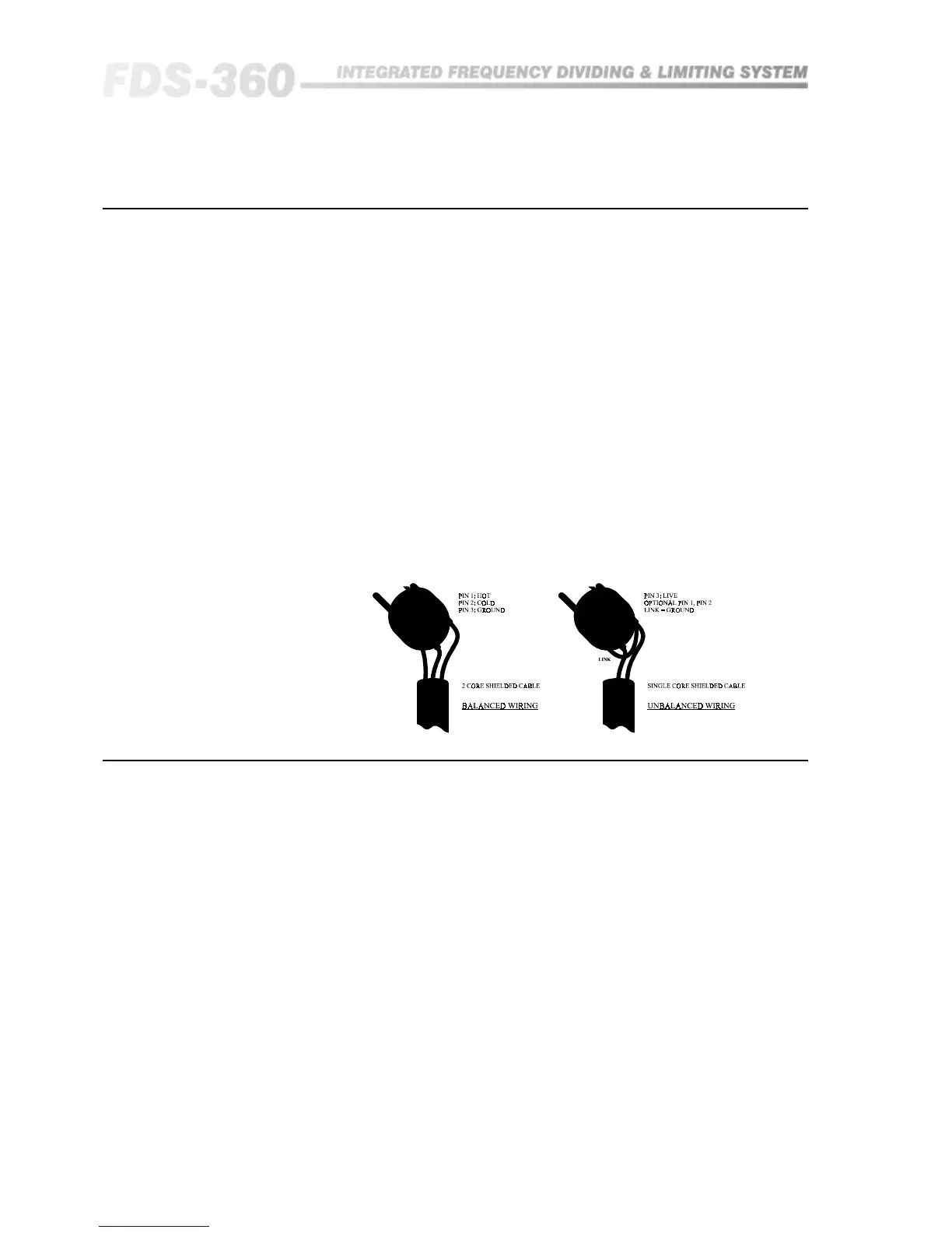
as follows: (See Figure 9.1a):
Pin 1: No connection (the shield of the drain wire can be terminated
here if desired).
Pin 2: Signal '-', out of phase or 'COLD'.
Pin 3: Signal '+', in phase or 'HOT'.
For unbalanced sources (See figure 9.1b):
Pin 1: Leave open, or link to pin 2.
Pin 2: Shield, braid, or screen wire.
Pin 3: Signal '+' or 'HOT' (inner core).
There is no internal ground connection to Pin 1 of the female XLR to avoid
possible interconnection earth loops. The input signal cable shield must
therefore be tied to ground, or signal 0V, at the source end.
9.1 XLR Plugs.
Fig 9.1 XLR Plug Wiring
10.0 Output Connections
10.1 XLR Plugs
The four signal outputs are DC blocked low impedance unbalanced from a
standard 3 pin male XLR and are designed to drive up to +20dBv into 600
ohms or greater. The wiring convention is as follows:
Pin 1: Connects to shield, screen or drain wire.
Pin 2: '-', cold or 'out of phase' output.
Pin 3: '+', hot or 'in phase' output.
If the amplifiers you are feeding have unbalanced (single ended) inputs, but
are fed from standard pin to pin XLR cables (See above), simply link the cable
at the crossover end as follows:
Pin 1: Connects to shield or screen wire.
Pin 2: Link to Pin 1.
Pin 3: Connects to the inner 'hot' or live core.
Unbalanced transmission is not recommended for connections to distant
equipment, but is generally acceptable for local connections within the rack,
or to an adjacent rack.