42
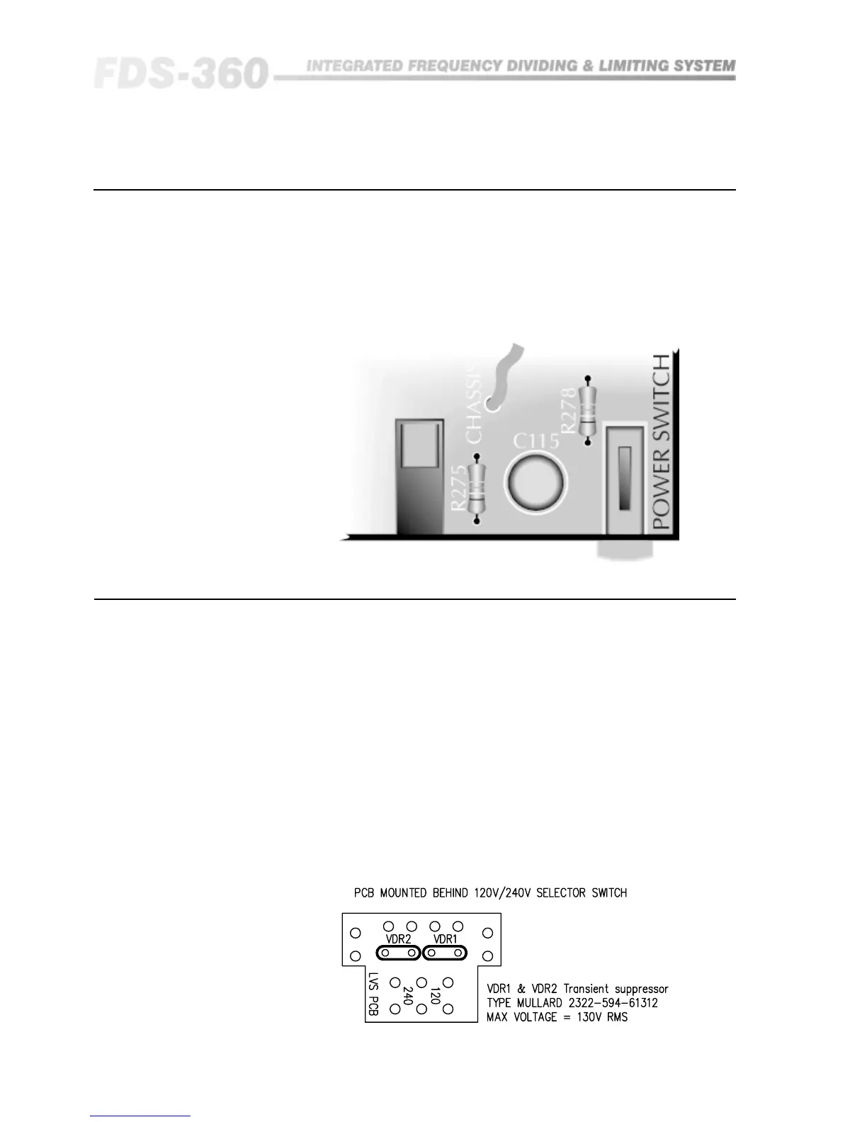
21.0 Electronic/Chassis Earth Link
In some installations it may be necessary to separate the electronic 0V from
the chassis and mains power earth to help in avoiding earth loops around the
unbalanced output connections. Should this become necessary, it is easily
achieved by removing a wire link inside the FDS-360. Figure 21.1 shows the
location of this wire link.
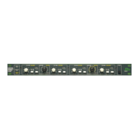
22.0 Transient Suppressor Replacement
The primary of the mains transformer within the FDS-360 is protected against
high voltage spike interference by two voltage dependent resistors. These
provide a short circuit to voltage peaks in excess of their maximum rating.
Should the FDS-360 be inadvertently connected to 3 phase line/line voltages,
or to 240V when selected to 120V, or any other incorrect voltage, these
suppressors are likely to fail in a protective short circuit mode. This will be
demonstrated by repeated mains fuse failure when powering up the unit.
Even in this case of extreme overvoltage, the FDS-360 is protected against
failure, and the simple removal of these suppressors will allow the unit to be
used again. However, it is important that they are replaced as soon as
possible to ensure continued protection.
Figure 22.1 indicates the location and specification for the suppressors.
Fig 21.1 Wire Link
Location
Fig 22.1 Suppressor
location
Transient Suppressor Replacement
Chassis Earth Link