36
20 50 100 200 500 1k 2k 5k 10k 20k 40k
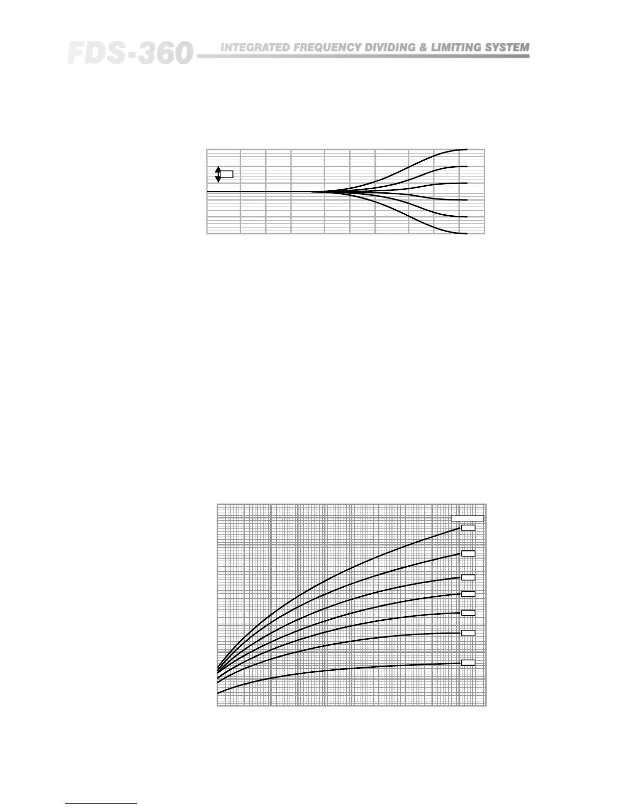
5dB
HF Shelf RQ = 0, Fc = 16kHz
Fre
(Hz)
20.6 Application of
the FDS-360D to a
system
A target response should be arrived at by either inspection from a set of
frequency response curves, or by adjustment of an external equaliser
connected into the system. For simplicity, only one frequency band of the
crossover has been considered.
Take a plot of the unmodified frequency response of the FDS-360 and on the
same sheet of graph paper plot the target response. A third plot is then drawn,
which is the difference, in dBs, between the two curves and this 'correction'
curve is the desired response of the FDS-360 equalisation section. From this
correction curve, the amount of dB boost or cut and the centre frequency, Fc,
are easily obtained by inspection. The required Q value can either be
obtained by calculation or estimated by comparison with the sample curves
provided with this manual.
The equation of Q of a Bell response curve is:
Q = Fc/(Fu - Fl),
where Fu and Fl are the frequencies at which the amplitude response is 3dB
down from the value at Fc.
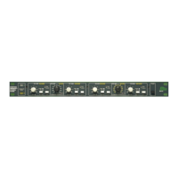
0 1k2k3k4k5k6k7k8k9k10k
0
0.2
0.4
0.6
0.8
1.0
1.2
1.4
1.6
1.8
2.0
2.2
2.4
2.6
2.8
3.0
Q
RQ (ohms)
16dB
14dB
12dB
10dB
8dB
6dB
4dB
QvsRQforVariousDe