(Hz)
Section B: Parametric Equaliser Filter.
This is a fully adjustable bell shape equaliser for which control is given over:
• Centre frequency
• Q, or the sharpness of the Bell shape
• The amount in dB of the boost or cut.
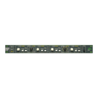
A sample response of this equaliser is shown in Figure 20.5:
1. Centre Frequency:
This is set by four components; Rfa, Rfb, Cfa and Cfb, and is given by the
following equation:
Fc = 1/[6.28 (R*fa/b . C*fa/b)], where R is in ohms,
C is in Farads,
F is in Hz.
For symmetrical and normal responses note that Rfa = Rfb and Cfa = Cfb, and
the equation reduces to:
Fc = 1/(6.28 x Rf x Cf)
Such that for Rfa = Rfb = 10k and Cfa = Cfb = 16nF than Fc = 1kHz.
Design limits for Rf should be within the range 2k to 100k ohms. There are no
limits for Cf apart from physical space on the circuit board.
2. Q and dB Boost/Cut:
Both of the parameters Q and dB are set by a single resistor, Rq and RdB
respectively. To some extent they are interactive and it is therefore easiest to
obtain their values from a set of graphs (See figure 20.10 and 20.11). These
allow for ranges of Q from 0.2 to 3.0 and for a range of boost/cut of up to
16dB.
For further information on deciding on the values of these filter variables,
refer to section 20.5.
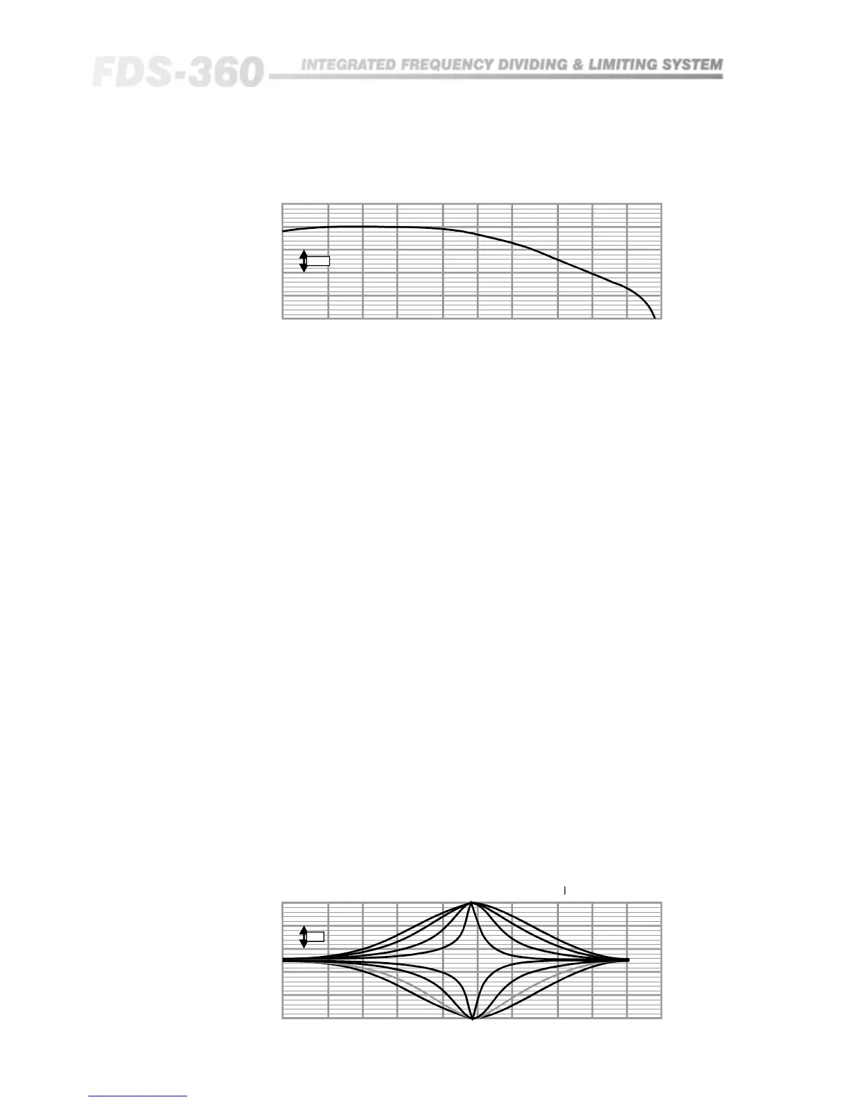
Fig 20.4 First Order
Sample Response
20 50 100 200 500 1k 2k 5k 10k 20k 40k
5dB
Bell Response RQ values, 0 , 1k , 4k7, = 12.5dB
Fre