3.2.3.2- Connection of the Auto kit
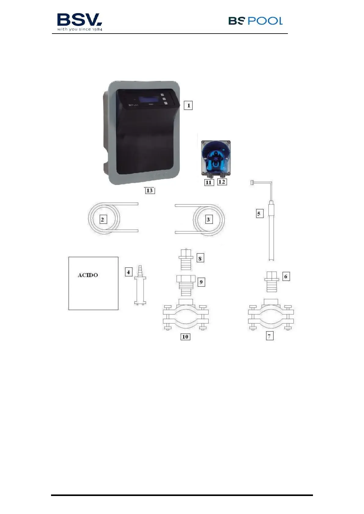
Once the equipment (1) is installed, the following connections should be done.
1- Place the flange (10) in the pipe as indicated in the hydraulic connection
diagram. The flange (10) corresponds to the injector and should be connected
after the electrolysis cell.
2- Place the flange (7) in the pipe as indicated in the hydraulic connection
diagram. The flange (7) corresponds to the PH probe and should be
connected after the electrolysis cell and before the filter.
3- Connect one end of the suction tube (2) to the PH control inlet (11).
4- Connect the other end of the suction tube (2) to the suction filter (4).
5- Place the suction filter (4) inside the ACID drum.
6- Connect one end of the suction tube (3) to the PH control inlet (12).