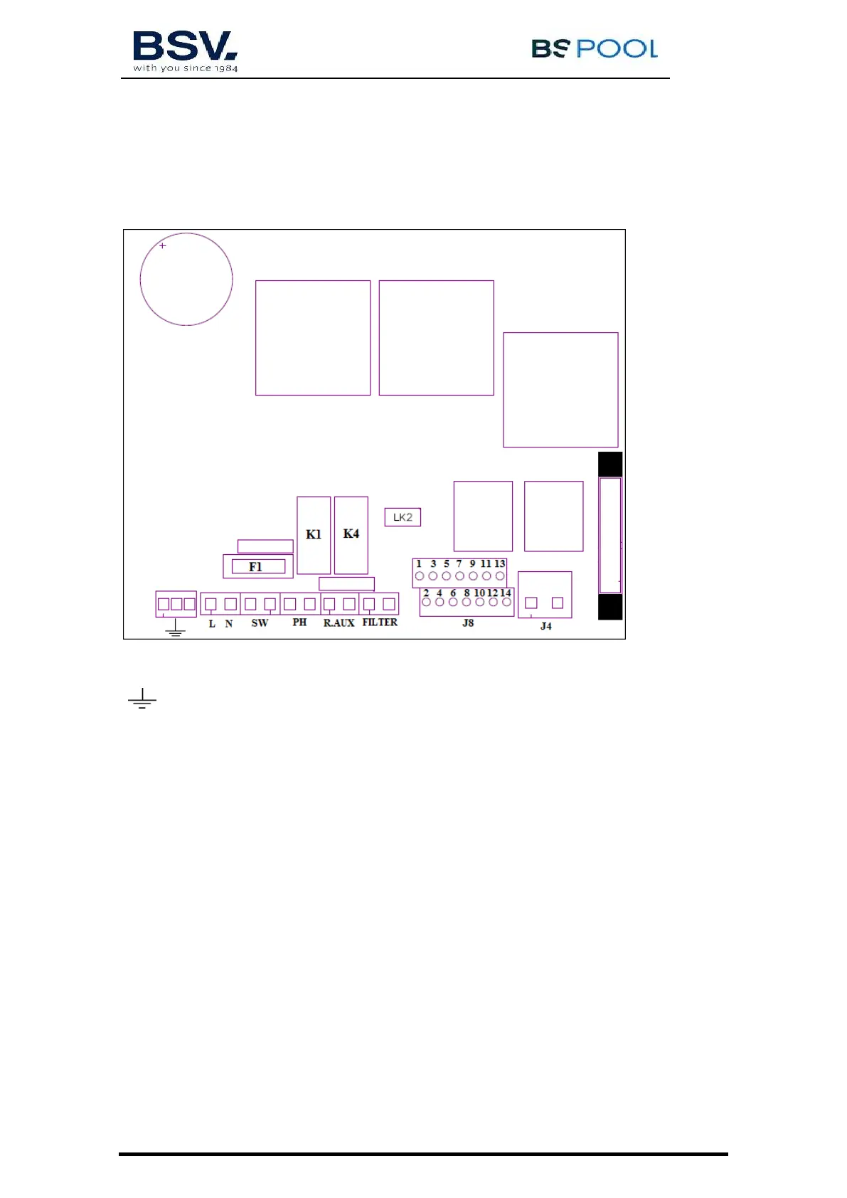
3.3- Electrical wiring diagram
3.3.1- PRO50/70 units
Earth connection
L, N: 230V mains
SW: ON/OFF Switch
PH1/PH2: Ph pump connection (for units with AUTO kit)
R.Aux: Auxiliary Relay
FILTER: Start / Stop input
J4: Cell connection
J8:
1- Acid level sensor (PH) 8-Temperature probe
2- Acid level sensor (PH) 9-ORP-
3- Cover 10-ORP+
4- Cover 11-12V for free chlorine
5- Flow sensor (white cable) 12-Conductivity
6-12V for the flow switch (between 5-6)* 13-Conductivity
7-Temperature probe 14-12V for conductivity
*Activate the
flow switch
function in the configuration menu
LK2: Start/Stop (See Pág. 54)