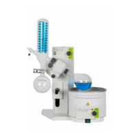
5.7.2 Connection to the cooling water sensor
1
2
3
4
5
6
a Silicone tube from the left
condenser (see Fig. 5.6)
b Outlet to chiller inlet
c Not used
d Angle
e Closed internal tube
f Impeller water meter with
cooling water sensor
Fig. 5.4: Connection to the cooling water sensor
To connect the cooling water sensor proceed as follows:
• Turn off the B-811 and disconnect it from the power supply.
• Disconnect the back board.
• Disconnect the internal tube e from the sensor and close it with a cable binder.
• Connect the silicone tube a (about 90 cm) to the angle.
• The silicone tube b will be connected to the chiller (see 5.7.4) via the back board (see 5.7.3).
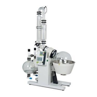
5.7.3 Rear connections
1
2
a Silicone tube from left con-
denser (see Fig. 5.6)
b Outlet to chiller inlet
Fig. 5.5: Rear connections
To establish the rear connections proceed as follows:
• Thread the silicone tube a through the back board.
• Connect the tube b to the chiller inlet, use an adapter if necessary.
• Connect the tube a to the left condenser (see 5.7.4).