7
Boiler block assembly
Logano G615 - Subject to technical modifications
25
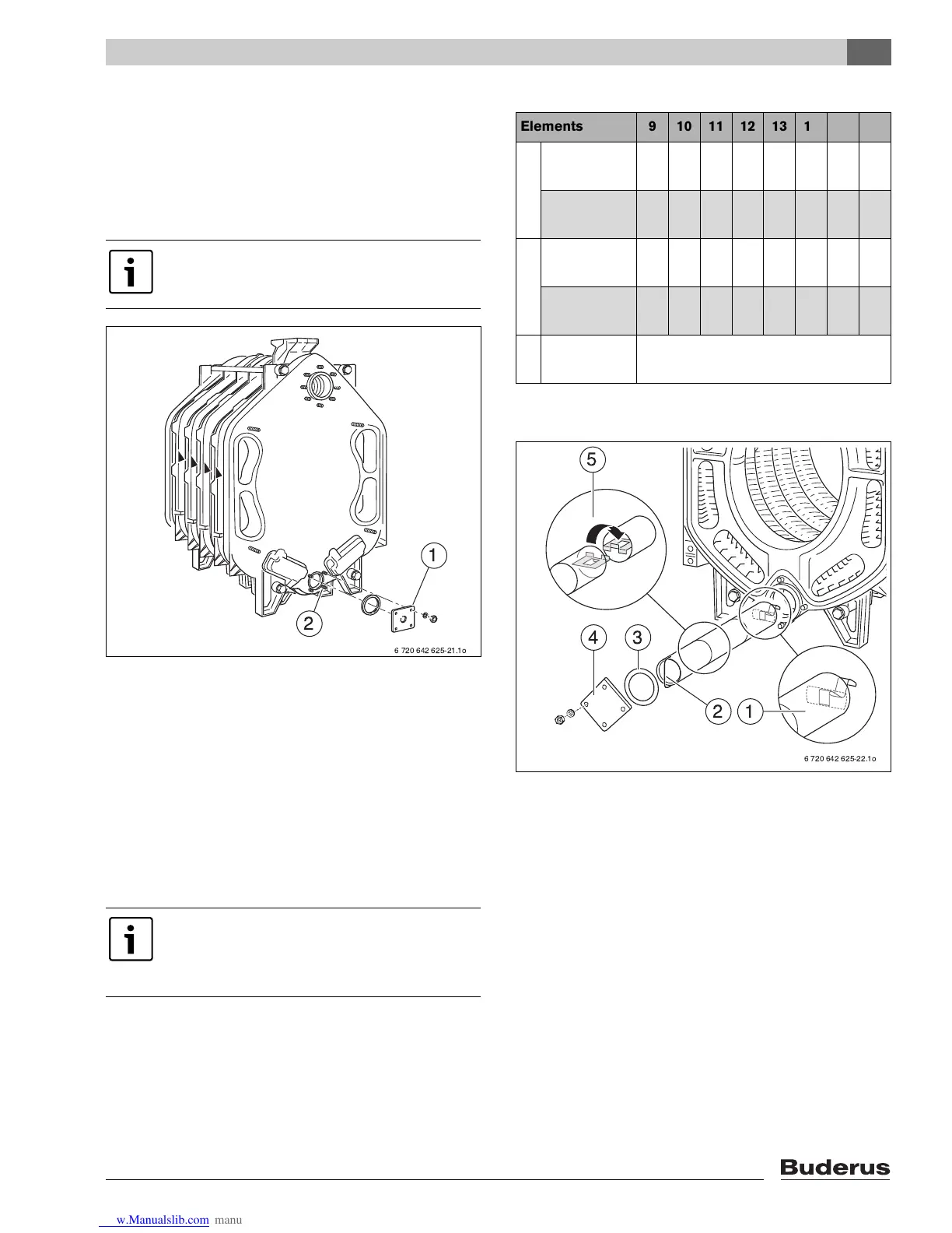
7.6 Inserting the lower distribution tube
(fittings crate)
B Mount the tapped hole for the drain connection on the
bottom boiler hub behind the flange
(edge length 5 – 1/8" (130 mm)) with R ¾ ".
B Fit customer-supplied boiler drain valve.
Fig. 24 Fitting the flange
1 Fill and drain connection
2 Bottom boiler hub (rear)
B Push the lower distribution tube element with spring
(L
3
) into the bottom boiler hub first.
B Hook the other lower distribution tube elements (L
2
)
into one another according to the detailed drawing.
B As the last lower distribution tube element, hook in the
one with the handle (L
1
).
B Close off bottom boiler hub with flat gasket and flange
cover.
Fig. 25 Inserting the lower distribution tube
1 Lower distribution tube element L
3
2 Lower distribution tube element L
1
3 Flat gasket
4 Flange cover
5 Lower distribution tube element L
2
The customer-supplied boiler fill and drain
valve is only used as a drain valve here.
The length and number of the lower
distribution tube elements depends on the
boiler size and can be determined using
Æ Table 10 below.
6 720 642 625-21.1o
2
1
Elements 9 10 11 12 13 14 15 16
L
1
18 29/32"
(480 mm)
1– – 1– 1– –
25 19/32"
(650 mm)
– 1 1 – 1 – 1 1
L
2
20 5/64" (510
mm)
1 1 – 2 2 – – 3
26 49/64"
(680 mm)
– – 1 – – 2 2 –
L
3
17 23/32"
(450 mm)
1
Tab. 10 Length and number of the lower distribution
tube elements
6 720 642 625-22.1o
12
34
5
 Loading...