Installation of the Exhaust and Air Intake System 10
25
We reserve the right to make any changes due to technical modifications!
Installation, Operation and Maintenance Manual Sealed Combustion Gas Boiler Logano GA244 • Issue 02/2004
Buderus Heiztechnik GmbH • http://www.heiztechnik.buderus.de
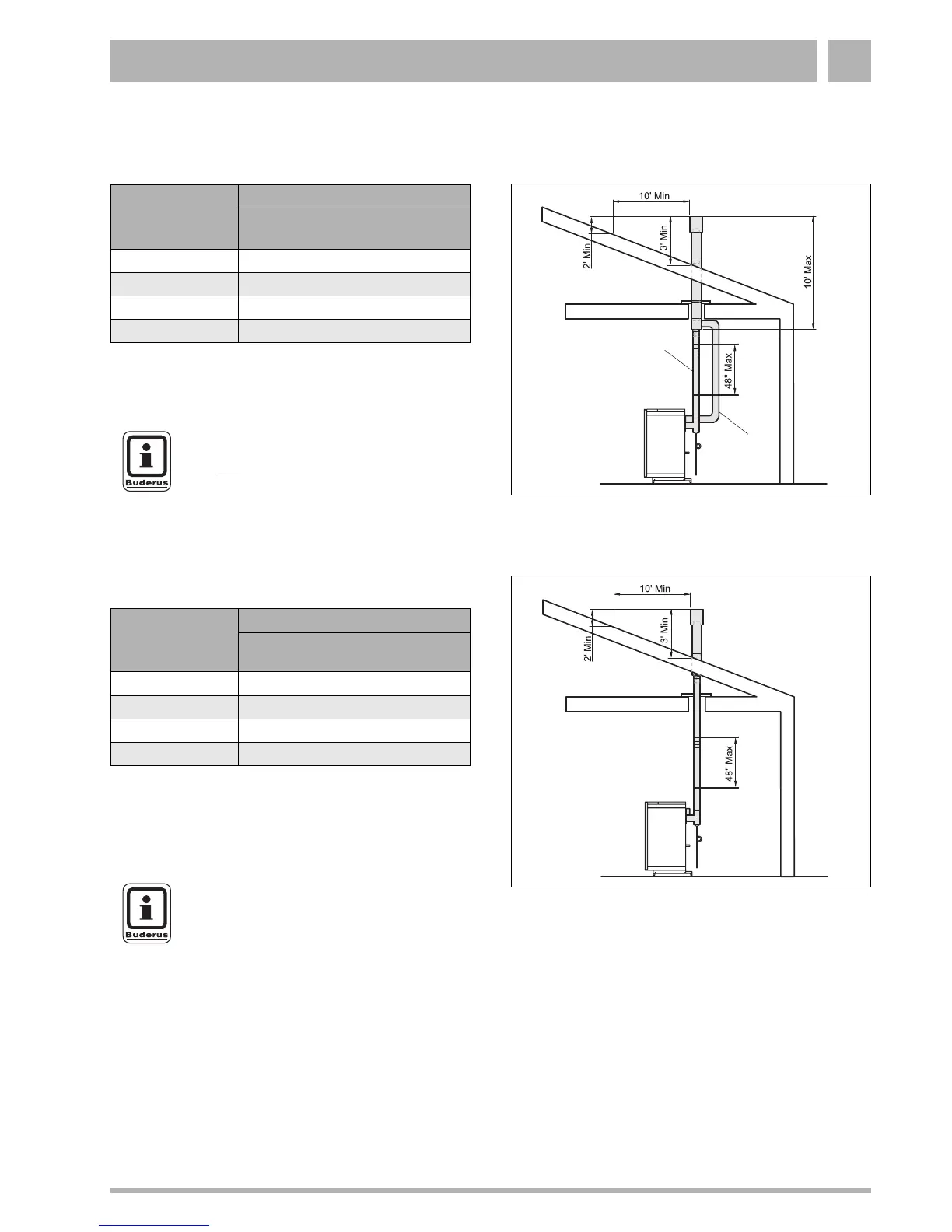
10.3.3 Sealed Combustion and Vertical Venting
Combustion air from outside the Building.
10.3.4 Room Air Configuration and Vertical Venting
Fig. 20 Vertical sealed combustion vent system
Item. 1: Exhaust vent pipe 3“ (models 37, 44 and 53)
Item. 2: Air intake pipe 4“
1
2
Sealed Combustion Configuration
Boiler
model
Exhaust vent pipe/
Air intake pipe
37 40 feet (max. 10 feet co-axial)
44 40 feet (max. 10 feet co-axial)
53 50 feet (max. 10 feet co-axial)
62 50 feet (max. 10 feet co-axial)
Table 9 Maximum equivalent length of exhaust vent pipe or
air intake pipe for vertical venting (
Fig. 20)
NOTICE !
Do not
exceed 10 ft concentric piping with
vertical termination.
Fig. 21 Vertical vent system for room air configuration
Item. 1: Exhaust vent pipe 3“ (models 37, 44 and 53)
1
Room Air Configuration
Boiler
model
Exhaust vent pipe
37 40 feet
44 40 feet
53 50 feet
62 50 feet
Tab. 10 Maximum equivalent length of exhaust vent pipe
for vertical venting (
Fig. 21)
NOTICE !
Vertical concentric piping is only required
for the length of the roof penetration.
Combustion air can be drawn then directly
from the boiler room.
 Loading...