EasyManua.ls Logo

Bulldog Security RS82 - User Manual

Bulldog Security RS82
8 pages
Print Icon
To Next Page IconTo Next Page
Loading...
CONTENTS
REMOTE STARTER MODELS RS82 AND RS85
INSTALLATION GUIDE
OWNER’S GUIDE
Technical Assistance
All tech personnel are expertly qualified to answer any technical questions.
Technicians are available Monday through Friday from 9:00 a.m. until 8:00 p.m. and Saturday 10:00 a.m. until 4:00 p.m.
Address
288 Canton Avenue • Wintersville, Ohio 43953
Telephone
Phone: 740-264-4710 • 800-878-8007 • Fax: 740-264-7306
System Features ..................................... 1
System Components ................................... 1
Required Tools ...................................... 1
Technical Assistance................................. 1
Before You Begin .................................. 1-2
Precautions......................................... 2
Using your Test Probe................................ 2
Making Wiring Connections .......................... 2-4
Locating & Making Connections ...................... 4-5
Connecting the 11-Pin Harness and the 4-Relay Harness ..6
Neutral Safety Switch ............................... 6
Operator Programming Instructions (RS82/85) ........... 6
Operator Programming Instructions (RS85 ............... 7
How to use Your Remote Transmitter.................... 7

Other manuals for Bulldog Security RS82

Question and Answer IconNeed help?

Do you have a question about the Bulldog Security RS82 and is the answer not in the manual?

Summary

Installation and Owners Guide for Remote Starters RS82;RS85

System Features

Two-Button Extended Range Remote Control

Remotely start your car to run the heater or air conditioning from an extended distance.

Two-Way Capability

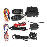
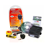
Works with your factory keyless remote transmitter or the included transmitter.

Parking Light Confirmation

Confirms that your vehicle has received a remote signal and will remain on if the engine is started.

Code Learning

Allows your remote starter to learn new remotes, should you want to add remotes, or if remotes are lost.

Pre Programmed Run Time

Unit is programmed to run for 15 minutes or stop at any time with the remote.

Pit Stop Mode

Allows you to exit the vehicle while the engine remains running.

Tach;Tachless Option

A programmable feature that lets you decide to choose the easy to install tachless operation.

Limited Lifetime Warranty

Guarantees life-long protection.

System Components

Required Tools

Technical Assistance

Before You Begin

Precautions

Using Your Test Probe

Making Wiring Connections

Wiring Connections: Stripping and Separating

Strip back wire insulation and separate vehicle wire for connection.

Wiring Connections: Inserting and Securing

Insert starter wires, wrap, and secure with tape and wire ties.

Making End to End Connections

End to End Connections: Stripping and Twisting

Strip, separate strands, and twist wires for end-to-end connections.

End to End Connections: Securing

Use electrical tape and wire ties to secure end-to-end connections.

Locating and Making Connections

Constant Power (+12 V)

Locate and connect to the vehicle's main ignition harness constant power wire.

Ignition Wire(s) (+12 V in Run;Crank)

Locate and connect to the ignition wire(s) that show +12V in run and crank.

Accessory Wire(s)

Locate and connect to accessory wire(s) that power the heater/blower motor.

Starter;Crank Wire (+12 V Start Only)

Locate and connect to the wire that shows +12V only in the cranking position.

Chassis Ground

Locate and attach the black ground wire securely to a chassis ground.

Connecting the 11-Pin Harness & 4-Relay Harness

Parking Light Output

Connect the yellow wire to the parking light wire for output.

Brake Input

Connect the blue with black stripe wire to the brake switch wire.

Antenna

Run the antenna wire straight and avoid metal parts or the vehicle computer.

Factory Alarm Shut Down Wire (FASD)

Connect the red with black stripe wire to the FASD wire to disarm the factory alarm.

Hood Pin Switch

Install and connect the hood pin switch to keep the engine from starting when the hood is open.

Tach Input

Connect the black with white stripe wire to the negative side of the coil for tach mode.

Auxiliary Input (Aftermarket Alarms)

Connect the blue wire to the second or third channel output of your existing alarm.

Auxiliary Input (RS85 Only)

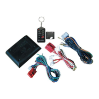
Connect to factory keyless entry system or aftermarket alarm.

Neutral Safety Switch

Mechanical Neutral Safety Switch (GM;Dodge pre-1996)

Use a circuit to prevent starting unless the key is removed from ignition.

Model RS82 Operator Programming Instructions

Adding Additional Remotes

Procedure to program additional remote controls to the system.

Tach;Tachless Option

Procedure to select between tach and tachless operation modes.

Model RS85 Operator Programming Instructions

Programming to Start with Factory Keyless Entry

Steps to program the system to start using your factory keyless entry.

Programming for Aftermarket Alarm Starting

Steps to program the system for starting from an aftermarket alarm.

Auxiliary Input (RS85)

Connect to factory keyless or aftermarket alarm systems.

How to Use Your Remote Transmitter

Button 1: Start;Stop

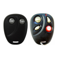
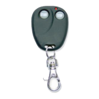
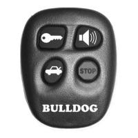
Press Button 1 to start or stop the vehicle.

Button 2: Stop

Press Button 2 to turn off your remote starter.

Pit Stop: Exiting with Engine Running

Allows exiting the vehicle with the engine running.

Bulldog Security RS82 Specifications

General IconGeneral
BrandBulldog Security
ModelRS82
CategoryRemote Starter
LanguageEnglish

Related product manuals