Page 23
SERVICE (cont.)
Location:
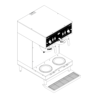
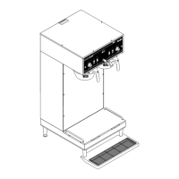
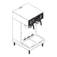
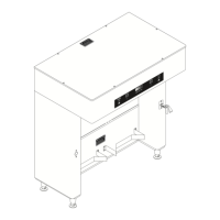
The electronic control assembly (1) is located
inside the lower left front on the component bracket of
the brewer. Access will also be needed to the tempera-
ture sensor (8), liquid level probe (7) located on the
tank lid and to the triac assembly (17) located beneath
the tank.
General:
This system controls the liquid level and water
temperature of the brewer. These two functions act
independently of each other and should be tested
separately.
ELECTRONIC CONTROL ASSEMBLY
!
C
A
U
TIO
N
H
O
T W
AT
E
R
.
M
INU
TES
BU
N
N-O
-M
ATIC
P
/N 262
0- 1
20 VAC
.
M
IN
U
TES
BUN
N
-O-M
A
TIC
P/N 2620- 120 V
AC
START
ON
/ WARMER
SELECTOR
RE
ADY
READY
O
N / WARMER
START
1
1
⁄2
gal
1
gal
1
⁄
2
gal
SELECTOR
1
1
⁄
2
gal
1 gal
1
⁄2
gal
C
A
U
T
IO
N
:
W
A
R
M
E
R
S
A
N
D
S
U
R
F
A
C
E
S
A
R
E
H
O
T
OFF
O
N
CAUTION
!
Failure To Comply Voids Warranty!
D
O
N
O
T
T
u
r
n
O
n
T
h
e
T
a
n
k
H
e
a
t
e
r
S
w
it
c
h
U
n
t
i
l
W
a
t
e
r
C
o
m
e
s
F
r
o
m
O
p
e
n
e
d
F
a
u
c
e
t
!
HAZARDOUS
VOLTAG
E
DISCO
NNECT FROM
POW
ER SOURCE
BEFO
RE REMOVING!
W
A
RN
IN
G
S
TO
P
READ NO
TICE
2 1
5
4
3
7 8 6 5 11
9
12
13
14
17
10
16 15
10. Recovery Booster
Relay
11. Contactor Assembly
12. Bypass Valve
13. Ready Light
14. Solenoid Valve
15. LED
16. Temperature adjust-
ment
17. Triac Assy
1. Electronic Control
2. Terminal Block
3. Timers
4. Liquid Level Switch
& Overflow Cup
5. Tank Heater
6. Limit Thermostat
7. Liquid Level Probe
8. Temperature Sensor
9. Dispense Valve
P783
27040 032201
FIG. 11 ELECTRONIC CONTROL ASSEMBLY