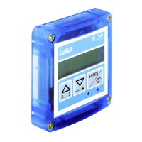
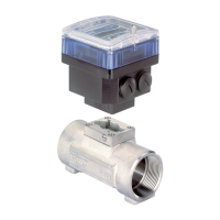
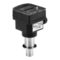
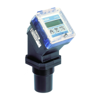
8025/8035 PROFIBUS-DP
E-1-
8025PRF/**
1 INTRODUCTION........................................................................................................ E2
1.1 Unpacking and Control ........................................................................................... E2
1.2 About this Manual ................................................................................................... E2
1.3 User's Responsibility for Safety .............................................................................. E2
1.4 Electromagnetic Compatibility ................................................................................. E2
2 DESCRIPTION........................................................................................................... E4
2.1 Specifications .......................................................................................................... E4
2.2 Electronic module 8035 PROFIBUS-DP external dimensions ................................ E5
2.3 Electronic module 8025 PROFIBUS-DP external dimensions ................................ E6
3 INSTALLATION ......................................................................................................... E7
3.1 Electrical connection type 8025/8035 PROFIBUS-DP 12/30 VDC ......................... E7
3.2 Connection of Siemens PLC to the transmitter type 8025/8035 PROFIBUS-DP.... E8
4 OPERATION .............................................................................................................. E9
4.1 Operating and Control Elements ............................................................................. E9
4.2 Operation Mode Display........................................................................................ E10
4.3 Calibration Mode ................................................................................................... E10
4.3.1 Address of the flow transmitter on the PROFIBUS-DP Net .................................E11
4.4 Test Menu...............................................................................................................E11
5 COMMUNICATION .................................................................................................. E13
5.1 PROFIBUS-DP master communication procedure ............................................... E13
5.2 Slave to master data transmission values ............................................................ E14
5.3 Master to slave data transmission values ............................................................. E15
5.4 Slave diagnosis frame values ............................................................................... E16
5.5 Master parameter frame for calibration ................................................................. E21
5.6 Examples of a message sent by the transmitter ................................................... E22
6 COMMISSIONING ................................................................................................... E23
6. Commissioning the PROFIBUS-DP network .......................................................... E23
Example 1: Configuration for PROFIBUS-DP network; PLC: IM 308 C ...................... E24
Example 2: Configuration for PROFIBUS-DP network; PLC: S7315-2DP .................. E25
7 MAINTENANCE....................................................................................................... E30
7.2 Error messages and maintenance ........................................................................ E30
7.1 Factory settings of the transmitter electronic 8025/SE35 at delivery ................... E30
TABLE OF CONTENTS
431693R/IND**/1198
