The SySTem
6
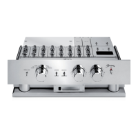
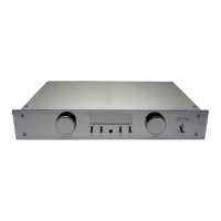
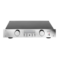
The 808 MK5 in brief
(1) POWER master switch for turning the power to the preamplifier on and off.
(2) POWER LED illuminates when the preamplifier has been powered up.
(3) SELECTOR knob - for switching between input modules and for activating the remote control
mode (REMOTE)
(4) MONITOR- / SOURCE- switch for comparing source and taped signal.
Requires the installation of at least one TAPE module.
(5) MONITOR 1 / MONITOR 2 - switch for comparing signals from TAPE 1 and TAPE 2. This switch is
only effective when the Monitor/Source switch (4) is set to Monitor.
(6) VOLUME - control knob for volume control of output modules OUTPUT 1 and SYM OUT 1.
The volume control is also effective when the REMOTE function has been switched on. As starting
point for remote control we recommend setting the knob to 12 (top center).
(7) VOLUME - control knob for volume control of output modules OUTPUT 2 and SYM OUT 2 (for
details refer to (6)).
(8) IR receiver must be left unobstructed for the remote to operate properly.
(9) Display shows the selected signal source and the volume setting in remote mode.
(10) Display - switch to switch display on or off.
(11) Input module mounting slots for installation of up to six input modules.
(12) Level control RIGHT for adjusting the right channel signal levels of the input modules.
(13) Level control LEFT for adjusting the left channel signal levels of the input modules.
(14) OUTPUT 1 - mounting slot for the unbalanced output module of output 1.
(15) OUTPUT 2 - mounting slot for the unbalanced output module of output 2.
(16) SYM OUT 1 - mounting slot for upgrading output 1 to balanced operation.
(17) SYM OUT 2 - mounting slot for upgrading output 2 to balanced operation.
(18) Level control RIGHT of the output modules to equalize right channel level variations of different
power amps and active speakers.
(19) Level control LEFT of the output modules to equalize left channel level variations of different
power amps and active speakers.
(20) OUTPUT 1 - switch to turn output module OUTPUT 1 on or off.
(21) OUTPUT 2 - switch to turn output module OUTPUT 2 on or off.
(22) Digital level display indicates the level of the selected input module in volts.
(23) Level display switch turn the level display on or off.
(24) Level display selector switch RIGHT/LEFT for switching between the channels.
(25) PHONO input L and R terminals for balanced phono connection.
(26) Mass screw for grounding tonearm cables with separate mass lead.
(27) AUX 1 - AUX 6 - inputs L and R. In the remote mode you can switch between the inputs AUX 2 to
AUX 6 by repeatedly pressing the AUX button on the remote control. Setting the SELECTOR
knob (3) to AUX switches only to the input AUX 1.
(28) Tape 2 - input, L and R, unbalanced.
(29) Tape 2 - output, L and R, unbalanced.
(30) Preamplifier OUTPUT 1, L and R, unbalanced.
(31) Preamplifier OUTPUT 2, L and R, unbalanced.
(32) PHONO input, L and R, balanced.
(33) CD input, L and R, balanced.
(34) TUNER input, L and R, balanced.