66
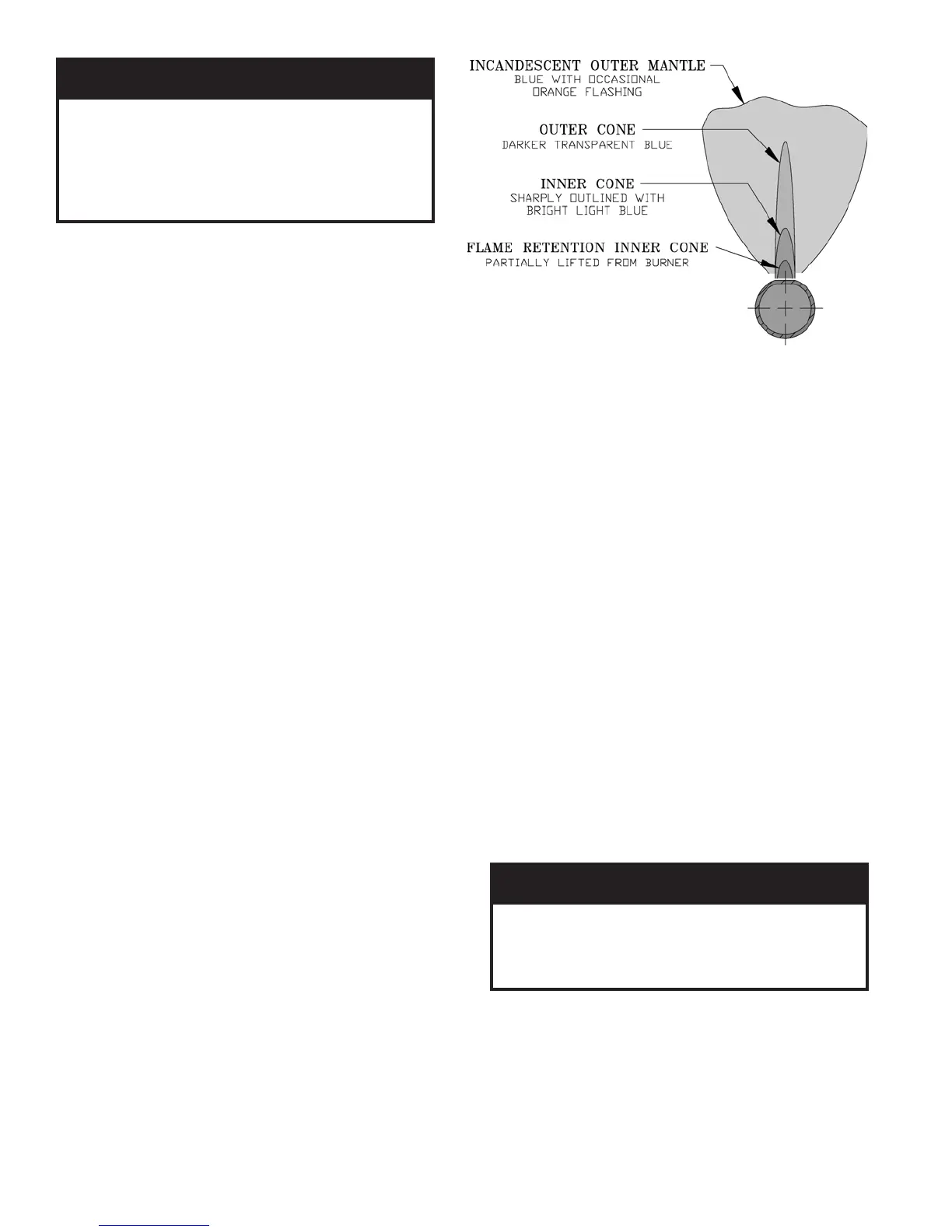
Yellow-tipping indicates lack of primary air. Improper
burner alignment on Main Burner Orifice will also
affect primary air injection. Adjust primary air as
follows:
a. Loosen lock screw.
b. Close air adjustment until yellow tips appear on
flames.
c. Slowly open air adjustment until clearly defined
inner cones are visible.
d. Tighten lock screw.
4. Adjust thermostat to normal setting.
J. Check thermostat or operating control operation.
Raise and lower temperature setting to start and stop
boiler operation.
K. Check ignition system shut-off.
1. Standing Pilot (24V): Disconnect thermocouple
lead at Gas Valve. Gas Valve must close and pilot
and main burners extinguish. If not, replace the
gas valve.
2. Honeywell EI: Disconnect ignitor/sensor cable
from Terminal (9) of ignition module. Gas valve
must close and pilot and main burners extinguish.
If not, measure voltage across gas valve terminals
"TH" and "TR".
a. If voltage is not present, replace gas valve.
b. If voltage is present, replace ignition module.
3. Johnson EI: Disconnect sensor cable from
Terminal 4 (SENSE). Gas valve must close and
pilot and main burner extinguish. If not, measure
voltage across gas valve terminals "TH" and "TR".
a. If voltage is not present, replace gas valve.
b. If voltage is present, replace ignition module.
4. EP and OP: Refer to instructions supplied with the
Honeywell RM7890 Burner Control.
L. Check Limit(s).
1. Adjust thermostat to highest setting.
2. Observe temperature gauge. When temperature
exceeds limit set point main burners should
extinguish.
Figure 59: Main Burner Flame
3. Adjust limit to setting above observed reading. Main
burners should reignite.
4. Adjust thermostat to lowest setting. Adjust limit to
desired setting.
M. Adjust gas input rate to boiler. Natural Gas.
1. Adjust thermostat to highest setting.
2. Check manifold gas pressure. Manifold pressure is
listed on rating label. Adjust gas valve pressure
regulator as necessary (turn adjustment screw
counterclockwise to decrease manifold pressure, or
clockwise to increase manifold pressure). If
pressure can not be attained, check gas valve inlet
pressure. If less than minimum gas supply pressure
listed on rating label, contact gas supplier for
assistance.
3. Clock gas meter for at least 30 seconds. Use Table
12 to determine gas flow rate in Cubic Feet per
Hour.
4. Determine Input Rate. Multiply gas flow rate by gas
heating value.
GNINRAW
lliwetartupnisagtsujdaylreporpoteruliaF
ehtfognirifrednurognirifrevonitluser
reliobefasnudnareporpmI.ecnailppa
.tluseryamnoitarepo
5. Compare measured input rate to input rate stated on
rating label.
a. Boiler must not be overfired. Reduce input rate
by decreasing manifold pressure. Do not reduce
more than 0.3 inch w.c. If boiler is still
overfired, contact your Burnham distributor or
Regional Office for replacement Gas Orifices.
NOITUAC
tnemnorivnenanireliobsihtgnitarepodiovA
yrd,srebifnoitalusniesool,tsudwaserehw
sireliobfI.tneserpera.cte,tsudllaw
renrubeht,snoitidnocesehtrednudetarepo
dnadenaelcebtsumstropdnaroiretni
.noitareporeporperusniotyliaddetcepsni
 Loading...