31
A.
Size gas Piping. Design system to provide adequate
gas supply to boiler. Consider these factors:
1. Allowable pressure drop from point of delivery to
boiler. Maximum allowable system pressure is ½
psig. Actual point of delivery pressure may be less;
contact gas supplier for additional information.
Minimum allowable gas valve inlet pressure is
indicated on rating label.
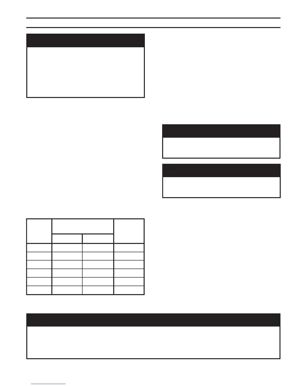
2. Maximum gas demand. Table 5 lists boiler input rate.
Also consider existing and expected future gas
utilization equipment (i.e. water heater, cooking
equipment)
3. Length of piping and number of fittings. Refer to
Table 6 for maximum capacity of Schedule 40 pipe.
Table 7 lists equivalent length for standard fittings.
V. Gas Piping
Table 5: Rated Input
4. Specific gravity of gas. Gas piping systems for gas
with a specific gravity of 0.70 or less can be sized
directly from Table 6, unless authority having
jurisdiction specifies a gravity factor be applied. For
specific gravity greater than 0.70, apply gravity
factor from Table 8. If exact specific gravity is not
shown choose next higher value.
For materials or conditions other than those listed
above, refer to the National Fuel Gas Code, NFPA
54/ANSI Z223.1 and/or CAN/CGA B149 Installation
Codes, or size system using standard engineering
methods acceptable to authority having jurisdiction.
B. Connect boiler gas valve to gas supply system.
relioB
ledoM
rebmuN
yticapaCdetaR
]ruohrepteefcibuc[
saG
noitcennoC
eziS
larutaNenaporP/PL
B5084625.5011
B6080332311
B7086935.8511
B80826457.4811
B90882552.1121
B0184955.7321
1. Use methods and materials in accordance with local
plumbing codes and requirements of gas supplier. In
absence of such requirements, follow the National
Fuel Gas Code, NFPA 54/ANSI Z223.1 and/or CAN/
CGA B149 Installation Codes.
2. Use thread (joint) compound (pipe dope) resistant to
action of liquefied petroleum gas.
3. Install sediment trap, ground-joint union and manual
shut-off valve upstream of boiler gas valve and
outside jacket. See Figure 26.
4. All above ground gas piping upstream from manual
gas valve must be electrically continuous and
bonded to a grounding electrode. Do not use gas
piping as a grounding electrode. Refer to the
National Electrical Code, ANSI/NFPA 70 and/or
CSA C22.1 Electrical Code.
GNINRAW
otylppussagepipylreporpoteruliaF
dnanoitareporeporpminitluseryamreliob
syawlA.erutcurtsroreliobehtotegamad
eerfkaelyletulosbasignipipsagerussa
ehtrofepytdnaezisreporpehtfodna
.daoldetcennoc
yamrotalugererusserpsaglanoitiddanA
.reilppussagtlusnoC.dedeeneb
GNINRAW
nosdnuopmocdaerhtreporpesuoteruliaF
foskaelnitluseryamsrotcennocsaglla
.sagelbammalf
GNINRAW
ebtsummetsysdnareliobotylppussaG
rognillatsniotroirpffotuhsyletulosba
.gnipipsagreliobgnicivres
ECITON
neebevahlevelaesevobateef000,2nahtretaergsedutitlatanoitallatsniroftliubsreliobASU
ehtreplevelaesevobateef000,1reptnecrep4etartupnisagecuderotdecifiroyllaiceps
'sreliobnaidanaC.FxidneppAdna2.1.8noitceS,1.322ZISNA/45APFN,edoCsaGleuFlanoitaN
ehtybelbaifitnedierasledomreliobedutitlahgiH.lebalgnitarehtnodetacidnisignizisecifiro
)'0005-'0002=5,'0054-'0002=4(.lebalgnitarehtnotigidhtnins'rebmunledom
 Loading...