40
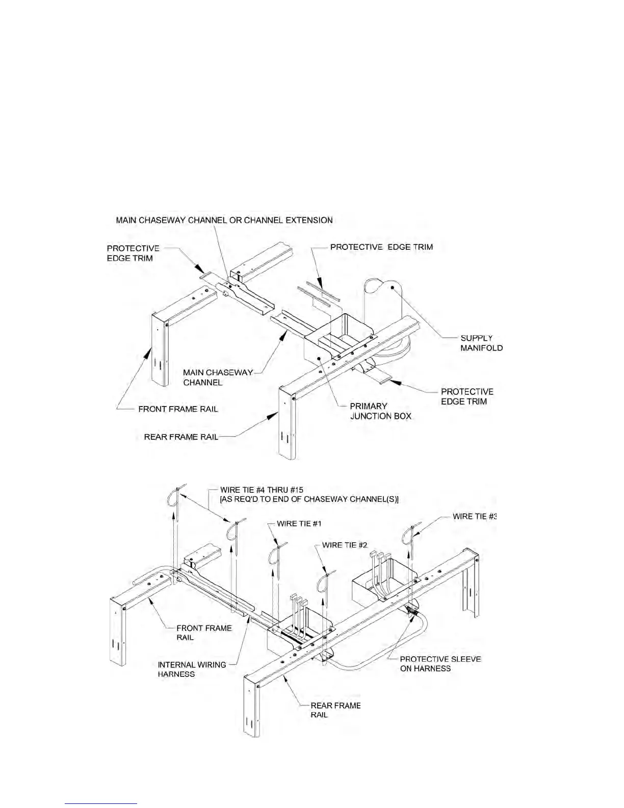
Figure 24e: Internal Wiring Harness Components - Install Protective Edging
Install 1-13/16” lg. pieces on horizontal raw edges
at both ends of chaseway channel assembly. Install
4-11/16” lg. pieces to vertical chaseway channel
anges inside primary junction box as shown in
Figure
24e.
5. Locate and install internal control/safety circuit
wiring harness. Start with harness end that has three
(3) connectors, insert connectors through rectangular
opening on front and rear of primary junction box.
Pull harness through J-box until second set of three
(3) connectors can be inserted through front opening
in J-box. Center connectors in primary J-box and
secure harness to chaseway using nylon wire tie No.
1, see Figure 24f.
Pull on harness to remove slack in J-box, secure
harness to end of chaseway channel using wire tie
No. 2 as shown in Figure 24f.
Figure 24f: Internal Wiring Harness Components - Install and Secure Harness to Chaseway