Installation | 5
0870201428_RA0165-0305D_O2_-0004_IM_en 17 / 36
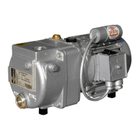
5.6.2 Wiring Diagram Temperature Switch "Oil" (Optional)
Part no.: 0651563747
Connector: M12x1, 4-pin
Electrical data:
U = ≤ 250 V AC/DC (50/60 Hz) ; I = ≤ 1 A
Switch point:
T
1
pin 1 + 2 = 110 °C*
T
2
pin 3 + 4 = 130 °C*
1 = Brown ; 2 = White ;
3 = Blue ; 4 = Black
* The switch point value depends on the oil type, see Oil [►31].
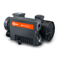
5.6.3 Wiring Diagram Resistance Thermometer (Optional)
Part no.: 0651563753
Connector: M12x1, 4-pin
Electrical data:
U = 10 … 35 VDC
4 ... 20 mA ► 0 ... 150 °C
Warning / trip signals: see Oil [►31].
1 = Brown ; 3 = Blue
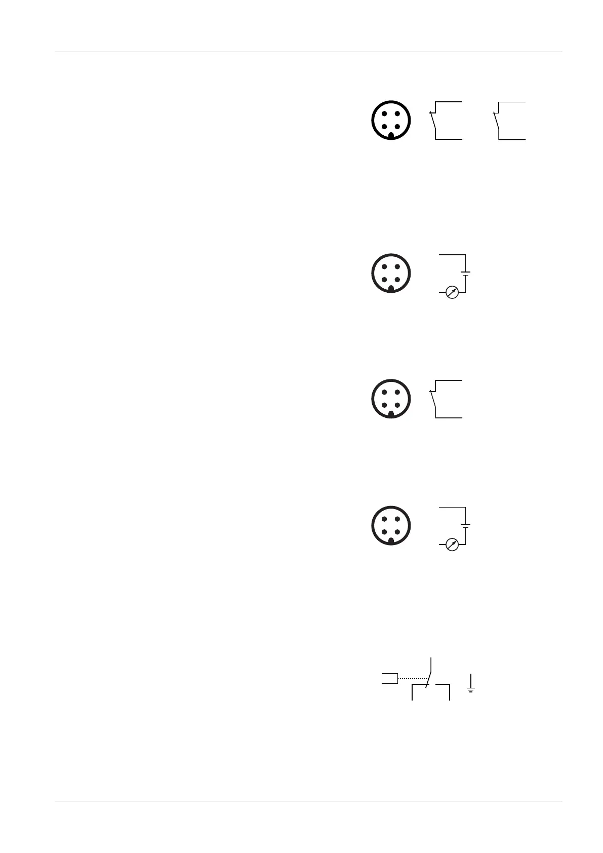
5.6.4 Wiring Diagram Pressure Switch (Optional)
Part no.: 0653563750
Connector: M12x1, 4-pin
Electrical data:
U = ≤ 250 V AC/DC (50/60 Hz) ; I = ≤ 4 A
Switch point:
P pin 1 + 2 = 0.6 bar (overpressure)
1 = Brown ; 2 = White
5.6.5 Wiring Diagram Pressure Transmitter (Optional)
Part no.: 0653 204 444
Connector: M12x1, 4-pin
Electrical data:
U = 10 ... 35 VDC
4 ... 20 mA ► 0 ... 1.6 bar (abs.)
1 = Brown ; 3 = Blue
Warning signal:
P
warning
= 0.4 bar (overpressure)
Trip signal:
P
trip
= 0.6 bar (overpressure)
5.6.6 Wiring Diagram Pressure Switch of Water-oil Heat
Exchanger (Optional)
Part no.: 0653000 002
Electrical data:
U = 230 VAC ; I = 1 A
U = 24 … 100 VDC ; I = 0.5 … 2 A
Contact: Normally open
Switch point:
P
trip
= 2 bar (relative) ► min. admissible
pressure