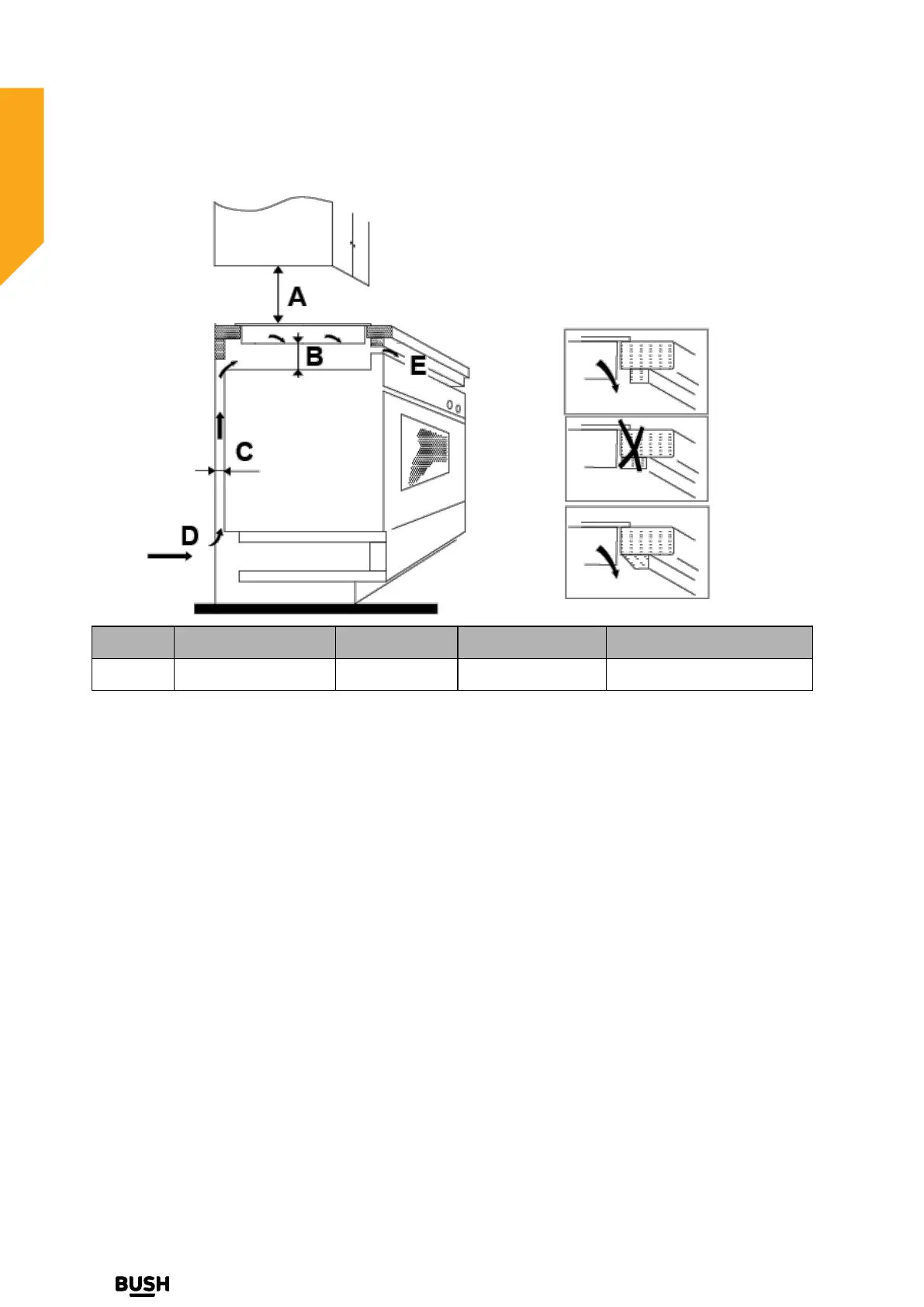
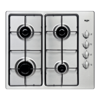
Installing your Built-in Hob
Bringing it all together
Installing your Built-in Hob
16
If you require any technical guidance or find that your product is not operating as intended, a simple solution can often be found in the Troubleshooting section of these instructions,
A(mm)
B(mm) C(mm) D E
760 50 mini Air Gap 20 mini Air intake Air exit 5mm
Before you install the hob, make sure that
• The work surface is square and level, and no structural members interfere with space requirements.
• The work surface is made of a heat-resistant material.
• If the hob is installed above an oven, the oven has a built-in cooling fan.
• The installation will comply with all clearance requirements and applicable standards and regulations.
• A suitable isolating switch providing full disconnection from the mains power supply is incorporated in
the permanent wiring, mounted and positioned to comply with the local wiring rules and regulations.
• The isolating switch must be of an approved type and provide a 3mm air gap contact separation in all
poles (or in all active [phase] conductors if the local wiring rules allow for this variation of the
requirements).
• The isolating switch will be easily accessible to the customer with the hob installed
• You consult local building authorities and by-laws if in doubt regarding installation
• You use heat-resistant and easy-to-clean finishes (such as ceramic tiles) for the wall surfaces
surrounding the hob.