5
BUTTERFLY™ ASSEMBLY
8. Make a final alignment of tubes (A) and (C), u-bolt (P) and spreader wires (D). Tighten nuts (V)
until flush with the ends of u-bolt (P) and no further.
NOTE: A slight bowing of tube (C) should be expected and will not harm anything.
9. At this point a second tube (A), tube (C), u-bolt (P) and a set of spreader wires (D) may be assem-
bled as in the preceding steps and attached to the other end of fiberglass insulator (B) to form a
complete Butterfly™ element.
Once all the parts are properly aligned, the hardware may be given a final tightening and the whole ele-
ment may be set aside temporarily.
10. Repeat procedures 1 through 9 for the assembly of the second Butterfly™ element, except that there
is no coil to be installed.
This completes the first part of the assembly process. Check your work to see that all parts are properly
aligned and that all of the hardware is tight. Note that the
capped
ends of the tubes (C) will be pointing
upward when the antenna is finished.
DRIVEN ELEMENT ASSEMBLY
NOTE: In the following steps, when you install clamps, apply a light coating of anti-oxide compound at
the spot where the clamp attaches to the tubing.
1. Take the Butterfly™ element with the coil (K) and place it on a flat surface with the threads of all
bolts facing upward.
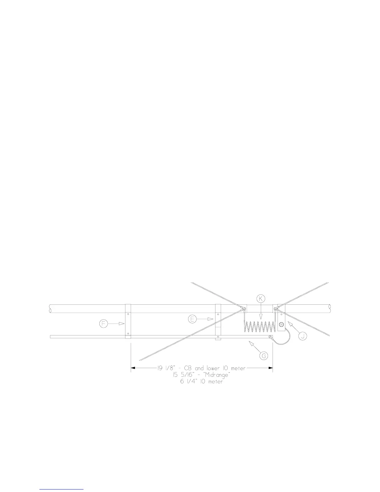
2. Install connector assembly (J) on the right side of the element with the threaded side of the connec-
tor facing you. Secure the connector assembly (J) to (A) with a 1 1/4" bolt (Z), lock washer (BB)
and hex nut (AA). Face the bolt upward, in the same direction as the others. The edge of connector
assembly (J) should be within 1/4" (6 mm) of the bolt holding the spreader wires (D).
3. Install spacer assembly (E) and gamma tap (F) on the left side of the element using 1 1/4" bolts (Z),
lock washers (BB), and hex nuts (AA). Point the threads upward and finger tighten only as you will
have to slide these along tube (A) in the following steps.
4. Attach tube (G) to the driven element as shown. Secure with 3/4" bolt (X), lock washer (BB) and
hex nut (AA).
5. Bend the wire coming from connector assembly (J), being careful not to break the soldered joint and
attach the lug to tube (G) with a 3/4" bolt (X), lock washer (BB) and hex nut (AA).
6. Align the tube (G) assembly so it does not contact spreader wire (D)
 Loading...